CHAPTER 1A - TERMINOLOGY
1- MECHANICAL ADVANTAGE (MA):
Mechanical advantage is a measure of the force amplification achieved by using a tool, mechanical device or machine system. The device preserves the input power and simply trades off force against movement to obtain a desired amplification in the output force. The model for this is the law of the lever. Machine components designed to manage forces and movement in this way are called mechanisms. An ideal mechanism transmits power without adding to or subtracting from it. This means the ideal mechanism does not include a power source, is friction less, and is constructed from rigid bodies that do not deflect or wear. The performance of a real system relative to this ideal is expressed in terms of efficiency factors that take into account departures from the ideal.
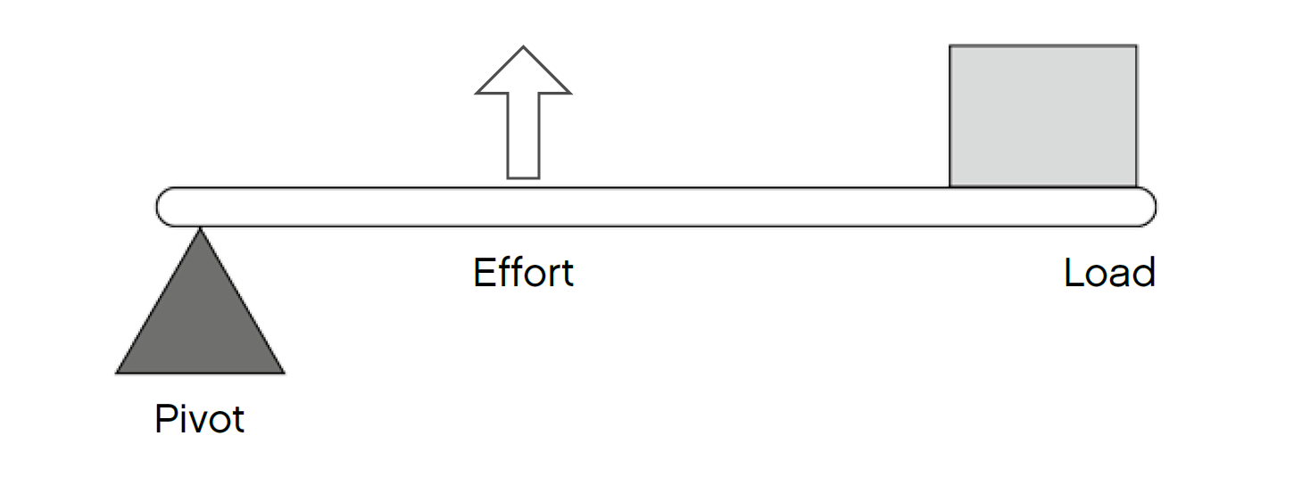
2- THE LAW OF THE LEVER (a first class lever system is depicted):
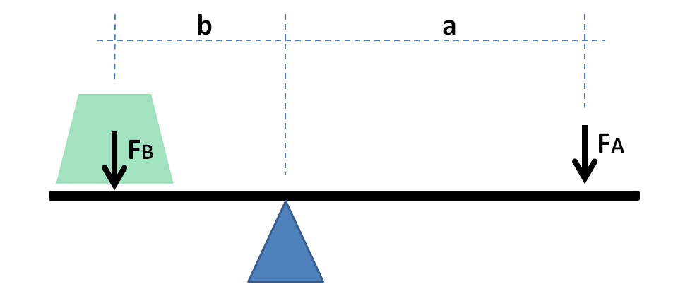
In a first class lever, the fulcrum is located between the load and the effort. If the fulcrum is closer to the load, then less effort is needed to move the load a shorter distance. If the fulcrum is closer to the effort, then more effort is needed to move the load a greater distance.
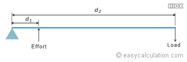
3-THE FORMULA USED TO CONFIGURE A SYSTEM MA: (referring to drawing above);
The lever is a movable bar that pivots on a fulcrum attached to or positioned on or across a fixed point. The lever operates by applying forces at different distances from the fulcrum, or pivot. As the lever pivots on the fulcrum, points further from this pivot move faster than points closer to the pivot. The power into and out of the lever is the same, so must come out the same when calculations are being done. Power is the product of force and velocity, so forces applied to points farther from the pivot must be less than when applied to points closer in. If a and b are distances from the fulcrum to points A and B and if force FA applied to A is the input force and FB exerted at B is the output, the ratio of the velocities of points A and B is given by a/b, so the ratio of the output force to the input force, or mechanical advantage can be known.
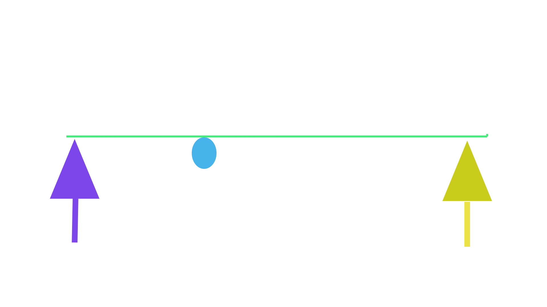
The experiments conducted on the lever systems presented bellow are using a similar method as the older type of balance (picture bellow) which is used to indicate the point at which the system is in equilibrium. The older type of scale use a first-class lever system where the fulcrum point is located exactly between the two weights. When two same size weights are placed on each end of the scale, the lever then moves to an orientation parallel to the horizon and indicates the equilibrium point. As stated by the formula above, when "a" and "b" lever lengths have equal distances from the fulcrum point, the system MA equals 1. It can then be concluded that when two same size weights are used in a system, the point where they are in balance or in equilibrium equals a system MA of 1. The experiments conducted bellow are performed on a second-and-third-class lever systems where two same size weights are used on every examples, thus when the two weights are in balance it indicates the point at which the system has an MA of 1.
4- HOW THE LEVER SYSTEM RELATES TO A GEAR-SET?
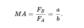
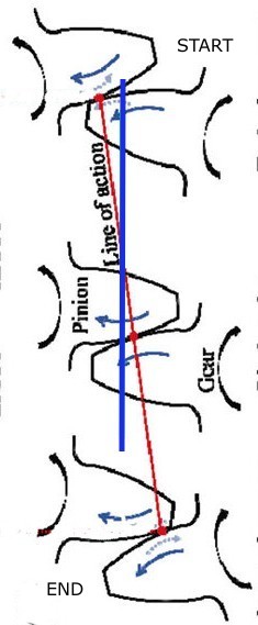
The drawing bellow depicts a conventional spur gear-set, the red and green lines illustrate two levers having equal distances on each side of their fulcrum. The MA and the Circular Pitch (C.P) can be configured by using the levers' specifications. This method was used to conceive the first gear-set ever invented as stated in the video above. We somewhat use that same principle to design the Custom gear-sets.
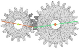
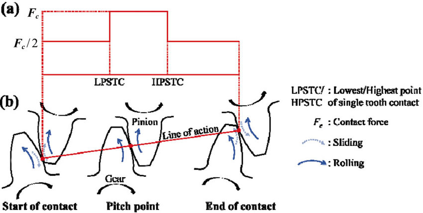
5- THE LINE OF ACTION, START OF CONTACT AND END OF CONTACT?
The drawing bellow depict a section of a gear-set: The angle at which the pressure is exerted between the teeth is named the "line of action" or sometimes also called "the pushing force angle".
The "start of contact" and the "end of contact" can be referred to either as "the lower and the upper operating angles" or as "the start and the end of the meshing stroke".
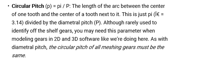
6- THE CIRCULAR PITCH OF A GEAR (C.P):
The Circular pitch (C.P) is the distance between two teeth. The last sentence in the paragraph bellow the picture states that the C.P of all meshing gears must be the same, consequently delivering a balanced power distribution from the Input to the Output of the system. Also note that both gears also need to have the same tooth shape.
The Custom gear-sets are designed to operate using different C.P on each gear and can use different tooth on each gear, consequently delivering an unbalanced power distribution from the Input to the Output of the system.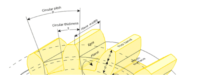
7- THE LINE OF ACTION OPERATION WITHIN THE CONVENTIONAL GEAR-SETS?
The line of action angle (or the pushing force angle) does not affect the system's MA since the lower and upper operating angles (start and end of contact) are cancelling each other out. This is because the line of action always averages an angle oriented perpendicularly to the horizontal axis (imaginary line relating both gears' centre). This aspect is illustrated in the drawing bellow where the yellow "bar" illustrates the line of action, and the vertically oriented blue line displays the line of action's averaging angle which is oriented perpendicularly to the horizontal axis relating both gears' centre (the red horizontal line). Which also means that the upper and the lower operating angle are evenly distributed on each side of the horizontal axis.
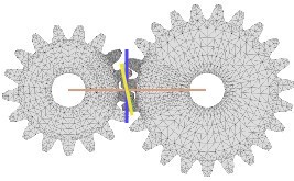
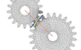
Even when the gear-set seems to be operating at different angles like in the drawing bellow, the average angle (blue line) of the line of action (yellow line) is still oriented perpendicularly to the horizontal axis (red line). The conventional gear-sets are all conceived to have the "start of contact and the end of contact" to occur evenly above and under the gears' axis which is the reason why both gears need to have the same Circular Pitch (C.P) and the same tooth shape in order to have fluent meshing between the engaging teeth. It can also be noted that the working distances travelled by both gears is equal to the C.P value.
These examples help to explain the fact that when configuring the Custom gear-sets, the true values to be entered into the formula such as the working distances travelled by the Input and the Output, and the line of action angle can only be obtained when the gear-set is rotated until the line of action averages an angle equal to the vertical axis. This step needs to be performed since the Custom gear-sets are designed to have different Circular Pitch on each gear, thus the working distances travelled by the Input and the Output do not equal the C.P values of the Drive and the Driven gears. They are also designed so the start and the end of contact are not evenly distributed on each side of the gear's axis which causes an unbalance power distribution from the Drive gear to the Driven gear. This fact is confirmed by results obtained from conducting experiments on fabricated embodiements (presented bellow).
If referring to the MA formula in terminology #3, it states that the system MA is simply determined by the lever lengths "a" and "b", where it is also used to calculate the system MA of the conventional gear-sets. It is only accurate because they all use the same method where both gears have the same C.P, thus the start and the end of contact are evenly distributed on each side of the horizontal axis, and also means that the average line of action angle is always oriented perpendicularly to the horizontal axis.
Since the Custom gear-sets uses different C.P on each gears the conventional formula cannot be used to configure the system MA. The reason is that the start and the end of contact are not evenly distributed on each side of the horizontal axis, thus they do not cancel each other out. Therefore, we cannot simply use the lever lengths "a" and "b" to configure the system MA since it doesn't consider that the different operating angles also affect the system MA.
The next picture is used to explain how the pushing force angles from the start to the end of contact are cancelling each other out in the common mechanisms. The drawing depicts the meshing stroke of a gear and pinion gear-set having a 1:1 speed ratio (same radius on both gears) where the blue vertical line represents the average angle of the line of action which is oriented perpendicularly to the horizontal axis. If the pinion is used as the Drive gear and rotates C.W, the start of contact will have an MA greater than 1 due that the point of contact is closer to the fulcrum than when at the end of contact where the MA will be proportionally less than 1, thus cancelling each other out so it doesn't need to be considered when configuring the system MA.
Per example if using the same gear set operation as above where the two gears have the same radius resulting in a system MA of 1 (according to the formula). Now if using 20 degrees of operating angles between the start and the end of contact, the start of contact will occur 10 degrees above the horizontal axis which provides an MA greater than 1 since the distance from the start of contact point to the gear's centre is less than the gear radius. The end of contact will occur 10 degrees bellow the horizontal axis which provides an MA proportionally less than 1 because the distance from the end of contact to the gear's centre is greater than the radius of the gear. The average lengths between the start and the end of contact points to the fulcrum is equal to the gear's radius. It can also be noted that at mid stroke the distance from the point of contact to the centre of the gear is equal to the gear radius. Therefore, since the start and the end of contact are evenly distributed on each side of the horizontal axis, the MA greater than 1 provided at the start of contact is cancelled out by the MA less than 1 provided at the end of the stroke, thus returning to an MA of 1 which doesn't need to be considered when configuring the Systems MA. These factors occurs in every conventional mechanisms.
If we use the same arrangement as above but instead use a Custom lever system having 20 degrees of operating angles, the start of contact would occur at 5 degrees above the horizontal axis, while the end of contact would occur at 15 degrees bellow the horizontal axis. Therefore, the stroke average MA would slightly less than 1 since 3/4 of the stroke is performed under the horizontal axis. Also note that the average distance between the start and end of contact points to the fulcrum point does not equal the gear radius. Therefore, this aspect also need to be accounted for when calculating the MA and the efficiency of the system and need to be added to the lever lengths "a" and "b" (or gears radius). In order to accomplish an unbalance distribution of the operating angles to occur on each side of the horizontal axis, both gears need to have different C.P (which we have the patent for). Note that the operating angles occurring on each side of the horizontal axis can vary from the example above, in fact sometimes the operating angles are distributed only to one side of the horizontal axis (explained in the next Chapters).
CHAPTER 1B-The First class lever different functions
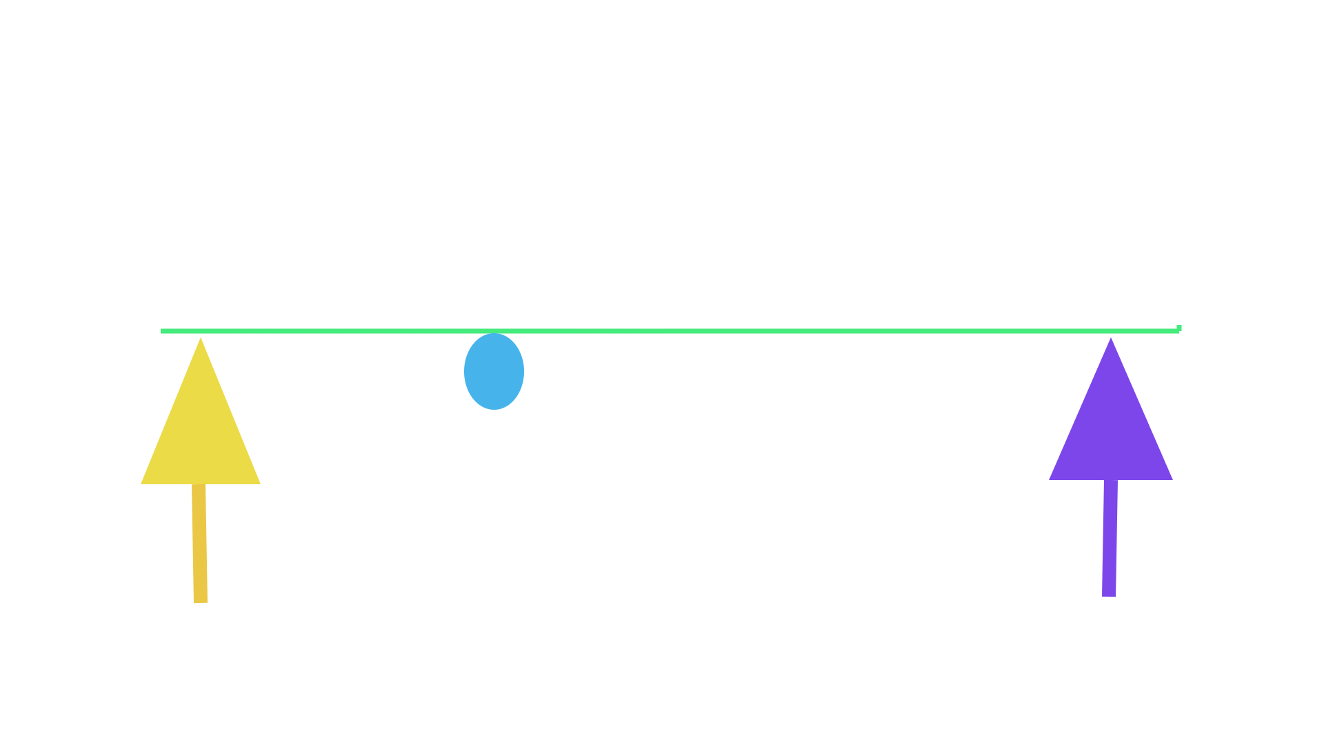
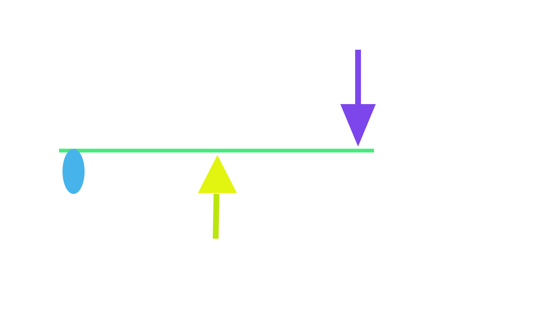
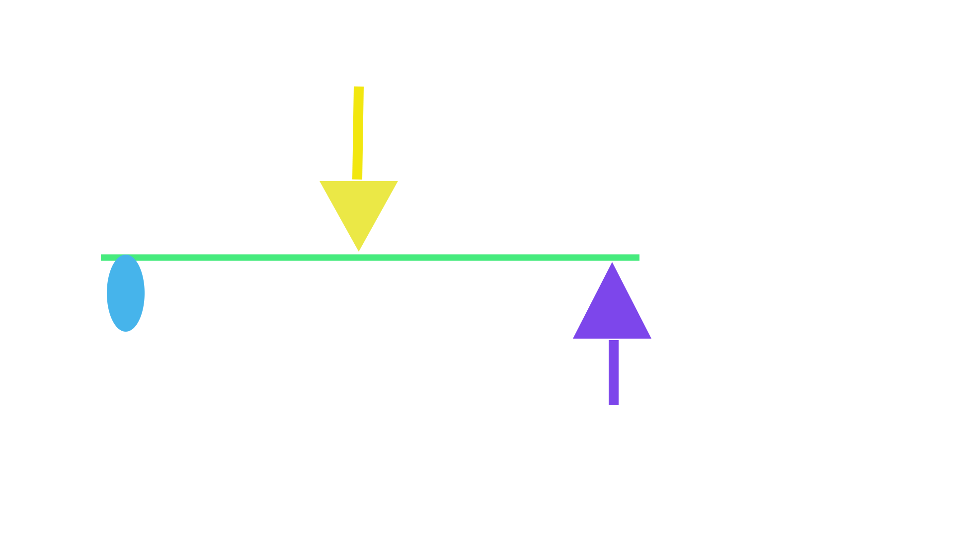
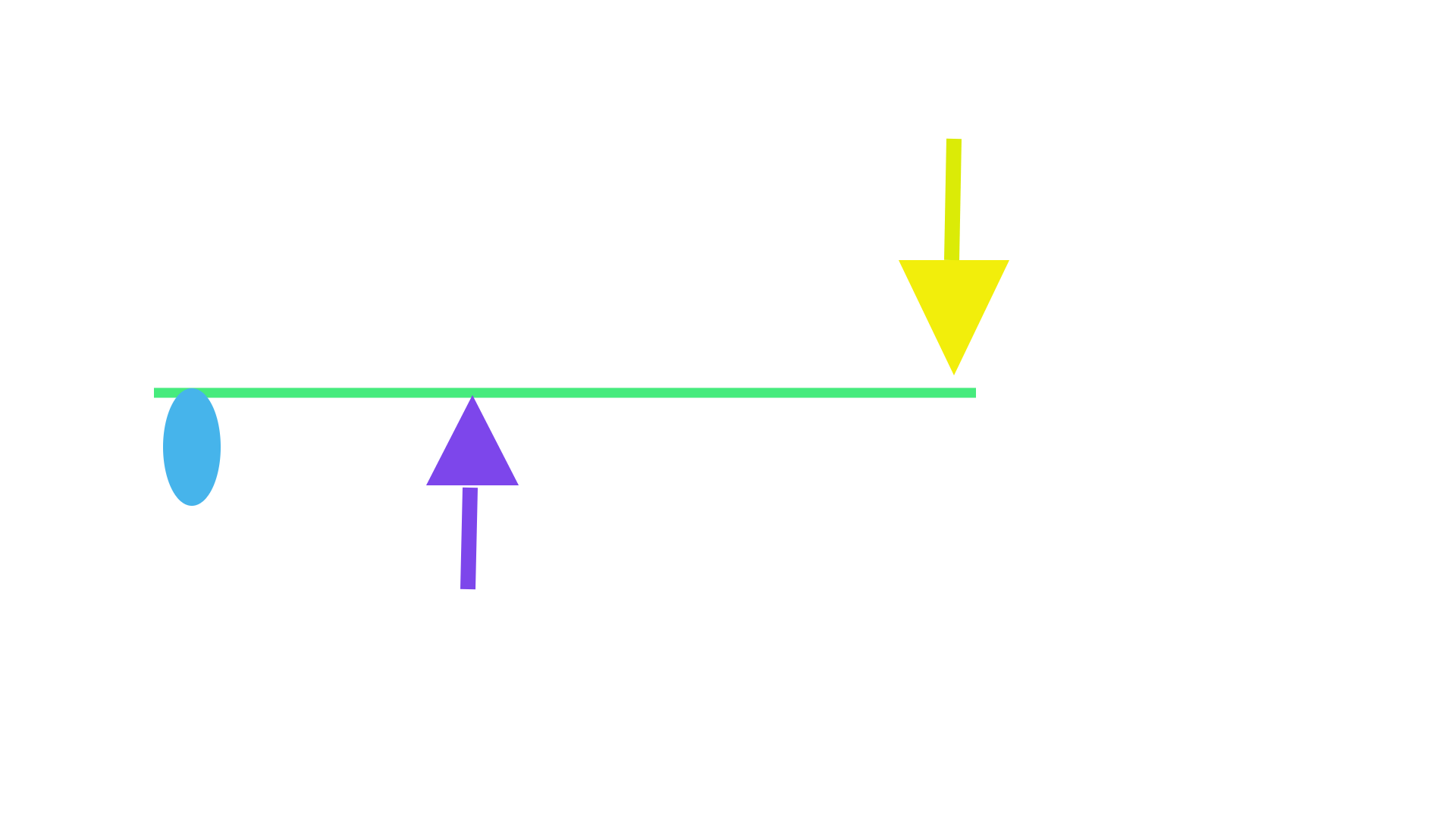
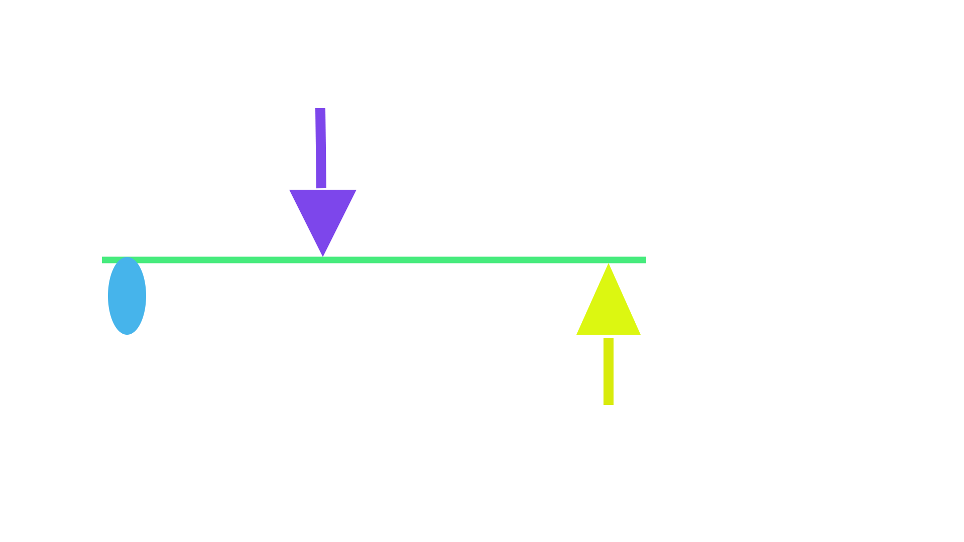
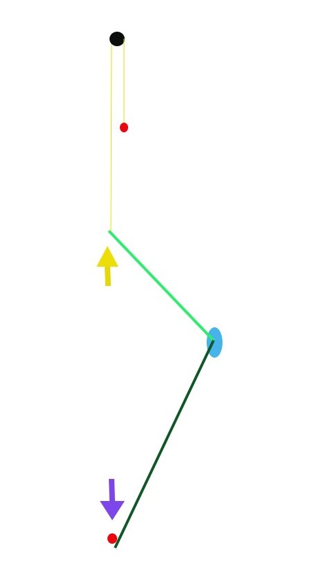
The drawings bellow are used to demonstrate that the first class lever system can provide up to four different functions which is an important aspect to consider when configuring the Custom mechanisms while not affecting the common mechanisms. The green line illustrates a lever, the fulcrum point is displayed as a blue oval shape and the yellow arrow is referred to as the Input side of the system while the purple arrow represents the Output side of the system. The arrows orientation demonstrates the direction of the exerted force applied on the lever.
EX-A EX-B
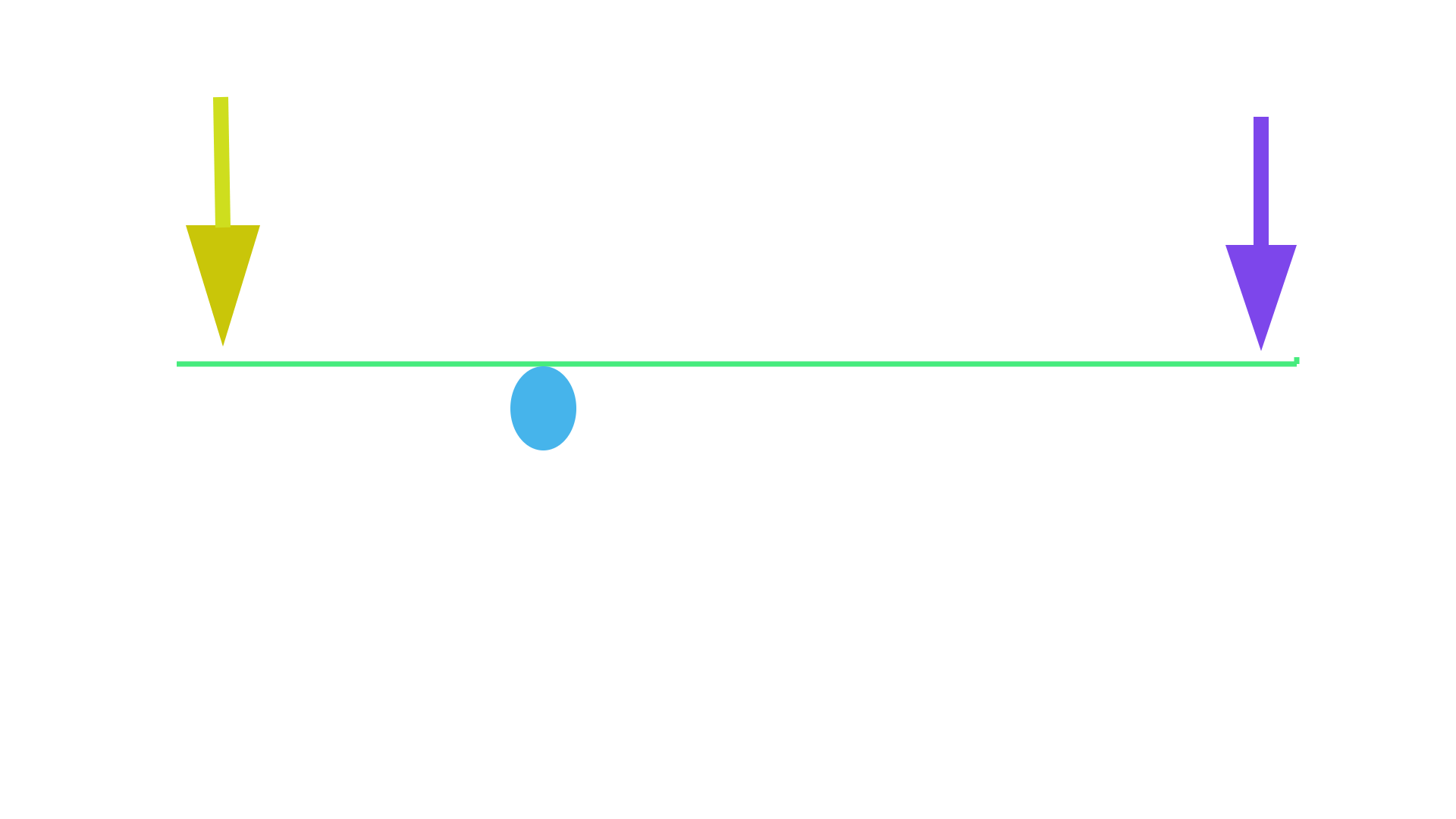
 EX-A EX-A demonstrates the first function that the lever can provide occur when a downward pushing force is applied to the Input side of the system providing an upward pushing force at the other end of the lever. It is important to mention that the purple arrow represent the downward counteracting force caused by a restriction. Per example a weight attached to the Output side of the lever exerting a downward pushing force on the lever.
EX-B demonstrates the second function that the same physical lever system can serve which occurs by simply interchanging the pushing forces direction from EX-A. The applied force is still performed on the same side of the lever but now the Input force is applied in an upward manner, consequently resulting in a downward pushing force at the other end of the lever. The purple arrow depicts an upward counteracting force caused by the Restriction. Per example a spring could be installed underneath the lever located at the Restriction (Output) point where the spring force pushes upward on the lever.
EX-C EX-D
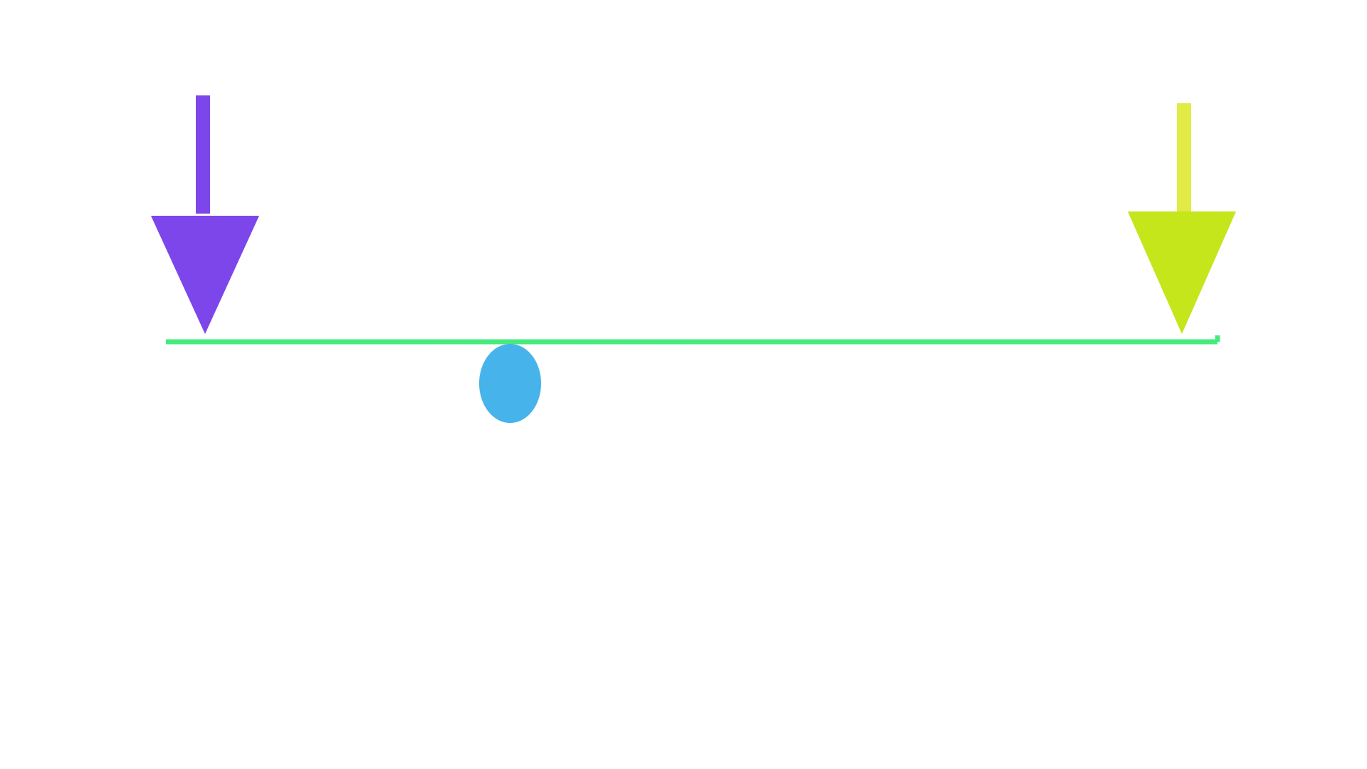
 EX-C depicts the third function that the same lever system can provide which occurs by simply interchanging the point where the force is applied to the system from EX-A. Now the Input side is located on the other side of the fulcrum where the force is still applied in a downward manner.
EX-D illustrates the fourth function that the lever can serve which occurs when interchanging the point where the force is applied to the system and also interchanging the pushing force directions from EX A. The force is now applied to the other side of the lever performing an upward pushing force.
According to encyclopedias when configuring the conventional mechanisms, the four functions the system can serve are all considered as different systems and are all calculated independently. While in reality the four functions the system can serve are all provided by using the same exact physical lever, technically the overall efficiency of the lever should be configured using all four functions efficiency combined. Although it is well known that the theoretical efficiency of the conventional mechanisms always equal 100%, thus the same result is prevailed if all functions are combined, thus their theory is accurate for the conventional mechanisms.
However, the conventional method to configure the efficiency doesn't work when using the Custom mechanisms since the efficiency of the four functions that the system can provide are not 100% efficiency. Every function that the system can serve need to combined in order to provide an overall system efficiency of 100%. The result of at least two functions (either A and B) or (C and D) have to be combined in order to determine the overall system efficiency. When using one function (A or C), the system will have an efficiency under 100% while the opposite function (B or D) will be proportionally over 100% (explain in details bellow).
According to the conventional theory every function the system can serve is considered as a different system. Per example if using a lever arrangement like in EX-A where the force is applied to the shorter side of the lever which has a 10" distance from the fulcrum and the Output side has 20" from the fulcrum, it is considered to be one system. However, if using a lever arrangement like EX-C where the longer side of the lever is used as the Input side, it is considered to be a completely different system even though it is only a different function that the same physical lever can serve. It is obvious that both functions should be calculated together as one unit, they are calculated like this;
Example #1- If the weakest side of the lever is used (as per EX-A) - using the shortest lever side (10") as the point where the power is supplied;
- MA = 10" / 20" = 0.5 MA
To configure the efficiency we needs to consider the Input and Output working distances travelled: the Input point travels half the distance of the Output point; If the Input point travels 1", the Output point will travel 2" . Therefore:
- Efficiency = (2" / 1") X 0.5 MA (as per step above) X 100 = 100%
Example #2- If the strongest side of the lever is used (as per EX-C) - the longest lever side (20") used as the point where the power is applied into the system;
- MA = 20" / 10" = MA of 2
Since the Input point travels twice the distance of the Output point; If the Input point travels 2", the Output point will travel 1". Therefore: -Efficiency = (1" / 2") X 2 MA X 100 = 100%
Every conventional gear-sets are configured like this, their method is accurate when configuring the common systems but it really should be calculated like when configuring the Custom systems:
= [100% (example #1) + 100% (example #2)] / 2 = 100 % where the efficiency average of both functions are combined.
Conclusion:
The common gear-sets have the same Circular Pitch (C.P) on each gears which causes the meshing stroke operating angles to occur evenly on each side of the horizontal cancelling each other out and don't affect the system MA which is the reason why every functions that the system can serve are all 100% efficient.
The Custom mechanisms use different C.P on each gear which causes the meshing stroke operating angles to occur at different angles on each side of the horizontal axis, so they do not cancel each other out and need to be accounted for since they affect the system MA. It is the reason why each function that the system can serve provides different system MA consequently affecting the efficiency. One function might have a 90 % efficiency while its opposite function will have 110% thus [(90 + 110) / 2] = 100% overall efficiency. It can then be concluded that the Custom systems are also respecting the law of conservation of energy.
The common mechanisms provide a balanced power distribution between the functions that the system can serve since it has the same C.P on each gear. While the Custom mechanisms provide an unbalanced power distribution between the functions that the system can serve which is provided when using different C.P on each gear. Although both types of mechanisms all have an overall system efficiency of 100%.
CHAPTER 1C- The second and third class lever system different functions
The custom gear-trains are derived from the Second-and-Third-class lever systems.
The operation of the common third-class lever:
It can be seen in the drawing above that the load point is located further away from the fulcrum than the effort point and is what defines the third-class from the second-class lever where its load point is located closer from the fulcrum than the Effort point.
MA = d2 / d1
The same formula as in the first-class lever is used to calculate the lever MA, only the lever lengths are used.
The third-class lever system can only serve two functions; when the pushing force direction are interchanged as in EX: E and EX: F
EX-E EX-F
Interchanging the point where the force is applied into the system results in a second-class lever as depicted bellow. The second-class lever system can also only serve two functions, depicted in EX: G and EX: H where the direction of the forces are interchanged. However, the same physical lever system is used on all four functions, only the direction of the forces and the point where the force is applied to the system are interchanged.
Second Class lever system
EX-G EX-H
 It can be noted that every lever system examples (EX-A to EX-H) are all classified as conventional systems which are illustrated when at the mid stroke position. The applied pushing force and the pushing force coming out of the system, the averaging line of action angle is oriented perpendicularly to the lever's horizontal axis. Therefore, every functions all have an efficiency of 100%.
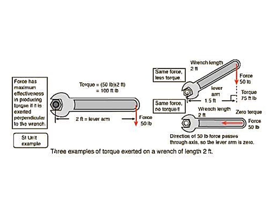
CHAPTER #2 - USING THE "WRENCH FORMULA" TO CONFIGURE SYSTEM MA
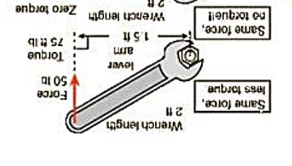
The formula used for top-right picture on the drawing bellow is used to determine how much force is prevailed at the nut when the wrench is oriented at the 2 O'clock position. The red arrow illustrates a downward pushing force which is performed vertically and not perpendicularly to the wrench axis.
The same picture can also be referred to a common lever system when operating at the start of contact, and since they operate evenly on each side of the horizontal axis it can be deduced that the end of contact would occur underneath the horizontal axis, at the 4 ' O'clock position.
The formula consists of using the Horizontal Distance (H.D) value between the Effort point and the fulcrum point and NOT the actual wrench length. This formula is referred to as the "wrench formula".

If 50 lbs of force is applied to the end of the wrench how much torque is exerted on the nut?
= 50 lbs X 1.5 Ft (H.D) = 75 Ft/lbs is applied to the nut.
The "wrench formula" can also be reversed if we have the value of the torque applied to the fulcrum and want to know how much force is transferred to the end of the lever (wrench). For example, how much weight can be lifted at the end of the lever if 75 Ft/lbs of torque is applied at the fulcrum?
= 75 Ft/lbs / 1.5'
= 50 lbs weight, really will be in balance with a 75 Ft/lbs torque applied at the fulcrum which represent the equilibrium point of the system.
It can be assumed that rotating the wrench 180 degrees like in the drawing bellow would prevail the same results as above since only the pushing force direction has been change. For the common mechanisms this is actually what occurs, however when using a formulated combination of lever angles, lever lengths and pushing forces direction something very particular occurs. It was found that exerting an upward pushing force at the end of the lever generates more force at the fulcrum point than when a downward force is applied. This fact is confirmed by the results obtained after conducting experiments on different types of mechanisms which are presented in the next chapters.
According to the "wrench formula" when the Effort point and the Restriction points have the same Horizontal Distance (H.D) from the fulcrum point, both forces are in balance and the system MA is equal to 1 regardless of the pushing forces direction and the lever angles. Per example if using a lever arrangement such as in the drawing bellow where the blue oval shape represents the fulcrum point, the green lines depict two levers, and the yellow line illustrates a rope which is passed over a pulley (in black). Two same size weights (red circles) are used as the Input and the Output of the system, the Input weight is attached to the rope end exerting an upward force on the lever while the Output weight is fixed on the lever end exerting a downward force on the lever. It can be seen that the Effort point (rope attached to the green lever) and the Load point have the same H.D from the fulcrum. Therefore according to the wrench formula, the weights are supposed to be in balanced and the system MA is equal to 1.
Every conventional mechanism (gears, levers, hydraulic jacks, tackle and block....) and every example used for teaching in schools are all using the theory of the lever laws explained above and is the reason why they state that every function that a system can serve are all theoretically 100 % efficient. In most mechanisms the theory works, however experiments conducted on fabricated Custom mechanisms confirms that there are exceptions to the rule.
It is important to note that the Custom lever systems presented bellow can all be converted into a gear-trains which provides much more useful applications then the lever system. The Custom gear-train can even be used to conceive a self sustainable generator and provide free energy since it the mechanisms provide over unity.
CHAPTER #3
This chapter explains in detail how the Custom mechanisms operates and the advantages over the conventional systems, it also confirms that the "lever law formula" as per Chapter #1A and the "wrench formula" cannot be used to configure the Custom system MA and efficiency.
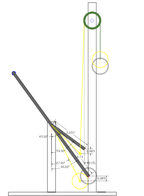
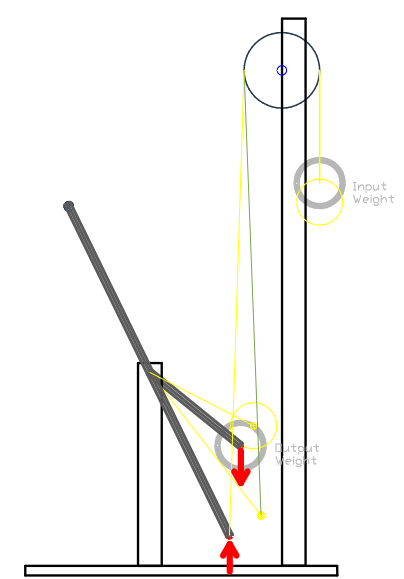
The drawing bellow depicts the embodiment shown in the next video where a third-class lever is used and has a "Y" shape (in black) which is required in order for the lever to be in a balanced state when both weights are removed from the system. This is achieved by attaching the proper weight size on the lever uppermost extremity (depicted by the blue circle) so that the lever remains still (in a balanced state). It is necessary to perform this procedure to accurately compare the force that the two same size weights are exerting on the lever. The red arrows are used to indicate the pushing force direction generated by the weights. A rope (in green) is attached to the shorter lever end, then passed over a pulley (the green circle) where a weight (the upper grey circle) is attached to the other end. Then another same size weight is fixed to the longer lever (the lower grey circle). To provide a third-class lever system the shorter lever must be used as the Input side of the system, therefore the Effort point is located where the rope is attached to the lever. The weight fixed at the end of the longer lever is then used as the Load point or the Restriction point (Output side of the system).
The Custom Lever & weights embodiment #1

The black lever represents when operating at the upper stroke and is the equilibrium point (both weights are in balance), therefore the system MA is 1 (as explained in Chapter 1A. The upper operating angle (end of stroke) is also the weakest point of the system. The yellow levers and circles represent the lever when operating at the lower stroke (start of stroke) and is the strongest point of the system and has an MA greater than 1. The experiment (shown in the next video) demonstrates that when the weight attached to the rope end (Input weight) is positioned at its upper position (depicted by the yellow upper circle), the weight will move downwards until the lever and (Output weight) reaches the upper stroke position until a balance between the weight is reached (end of stroke) which confirms that the weight attached to the rope has more force than the weight fixed on the longer lever for the whole stroke. It can be concluded that the system MA must be greater than 1.
The lower angle is set to have both weights to travel the same working distances (Vertically measured Distance), in this example the V.D equals 0.389". This fact contradicts the lever law theory since the weight attached to the rope is the strongest while both weights have the same working distances, resulting in an MA greater than 1. The lever law states that if two same size weights travel the same working distance, the system MA must be equal to 1 (also as per older type of scale explained in chapter # 1A). However, this embodiment doesn't contradict the law of conservation of energy as will be explained bellow.
The video bellow depicts the Custom lever mechanism arrangement illustrated above and demonstrates that when using a specially configured combination of pushing forces direction, lever angles and lever lengths, a different outcome than what occurs when using the conventional mechanism is prevailed. The embodiment in the video has the same specifications than on the drawing bellow.
The video demonstrates that when the lever is at the upper operating angle (end of the stroke), both weights are in balance thus having a system MA of 1. When the lever is oriented to the lower operating angle, the Input is stronger than the Output weight since it moves the lever and Output weight upwards. It can also be seen that when the system is operating at the upper stroke that the Load point has a greater H.D (Horizontal Distance) from the fulcrum than from the Effort point to fulcrum (o.151" H.D). This fact contradicts the wrench formula theory since it states that the weights are in balance only when H.D from the Input to fulcrum and from the Output from the fulcrum have equal distances.
The Custom third class lever system uses two same size weights where the two weights are in balance when the Load point has a greater H.D from the fulcrum (0.151") than the Effort point to the fulcrum. It is important to note that both weights are also travelling the same working distance 0.389" V.D which is used to determine the system efficiency as per Chapter #1B example #1 and #2, and since the system MA is greater than 1 at lower stroke and has an MA of 1 at upper stroke, it confirms that the efficiency is over 100%.
The reason why the Custom mechanism perform differently since the special combination (as explained earlier), in terms when the pushing force is performed upward provides more force than when it is performed in a downward manner (explained in details bellow). This phenomenon does not occur in any conventional mechanisms.
To configure the Custom mechanisms, a different formula than the "lever law formula" and/or the "wrench formula" must be used. After fabricating and conducting a large number of real-life experiments on these types of mechanisms we found a formula that corresponds to what occurs in real life in each and every embodiment we fabricated. This formula cannot be found in encyclopedias or anywhere on the web:
To calculate the mechanism discussed above we need to use the next formula and use the specifications prevail in the next drawing which illustrates the exact same embodiment as used in the video:
The Custom Lever & Weight embodiment #1 specifications
The first step consists of configuring the system MA when the forces are at the closest point to be in balance with each other, either at the lower or at the upper lever operating angle. As demonstrated in video, the end of the stroke is the weakest point in the system and where both weights are in balance thus, to calculate:
@ Upper stroke:
Step #1- Determine the Input Horizontal Distance from the Effort point to the fulcrum: = Sin 54 X 3.257" (lever angle and actual lever length) = 2.63497" (H.D)
Step #2- Determine the Output Horizontal Distance from the Load point to the fulcrum: = Sin 36 X 4.74"(lever angle and actual lever length) = 2.7861" H.D
Step #3- Use the Input actual lever length divided by the Output H.D and multiply by the Input H.D divided by the Output actual lever length:
= 1.16902 (3.257" Input actual lever length / 2.7861" from Step#2) X 0.5559 (2.63497" from Step #1 / 4.74" Output actual lever length)
= 0.6499
Step #4- Use the Input H.D divided by the Output H.D and multiply by the Input actual lever length divided by the Output actual lever length:
= 0.9457557 (2.63497" from Step #1/ 2.7861" from Step #2) X 0.68713 (3.257" Input actual lever length / 4.74" Output actual lever length)
= 0.6499
Step #5- Find the system MA (@ upper stroke) using Step #4 divided by Step #3:
- MA @ upper operating angle: = 0.6499 VS 0.6499 = MA of 1
Note that this step can only be used if the values are exactly the same since the formula is NOT used to calculate the system MA, it only indicates how close the weights are from being in equilibrium. If the values are exactly the same it means that the weights are in balance and the bigger the difference between Step #3 and Step #4, means that the weights are further away from being in equilibrium (explained in details in Chapter #5.
To calculate the system MA at the strongest point in the system which is the lowest operating angle since the Input weight is able to lift the Output weight as can be seen in the video.
@ Lower operating angle:
Step #6 - Determine Input H.D distance when at lower stroke: = Sin 45 X 3.257" = 2.303" H.D
Step #7 - Determine Output H.D distance when at lower stroke: = Sin 27 X 4.74" = 2.1519" H.D
Step #8- Use 2.7861" (From Step #2) - 2.63497" (from Step # 1) = 0.1513" + 2.303" (from Step #6) = 2.45413 This step is needed since we need to reset the balance point since it usually happens when both weights have the same H.D from the fulcrum point, although when using the Custom mechanism the balanced occurs when Input and Output H.D is further from the fulcrum (0.151") than the Input point. Therefore, this factor must be accounted for which is done by subtracting steps #2 and #1, and adding the result to Step #6, thus resetting the value where balance point occurs (explained in details and confirmed in chapter #5 example #1).
Step #9 -Find system MA at lower stroke using Step #8 divided by Step #7:
- MA @ lower operating angle = 2.45413" (Step #8) / 2.1519" (Step #7) = 1.14 MA
Step #10 - Find the Overall system MA using Step #5 added to Step #9 then dividing the answer by 2:
- Overall MA = (1 MA Step #5 + 1.14 MA Step #9) / 2 = 1.07 MA
Step #11 - Determine the system efficiency (when the system is used in the function described above (using the weight attached to the rope as the force applied into the system where the pushing force is performed upwardly while the Load is pushing down on the lever):
Efficiency = (0.389" Output V.D / 0.389" Input V.D) X 1.07 (from Step#10) X 100 = 107% (note that the same size weights are used).
As mentioned earlier the Custom lever system can be converted into a gearbox (see drawings bellow).
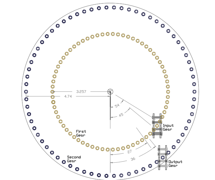
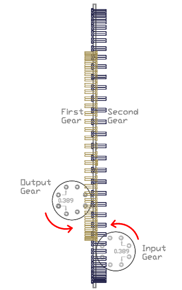
Custom Gearbox example #1: In order to convert the lever system into a gear-train, 4 gears (two gear sets) have to be used in order to completely be able to use all of the specifications in the drawing above, The Input side of the lever system is used to design the First gear, and the Output side is used to configure the Second gear. The First gear is fabricated to have 3.257" radius which is the same lever length (Effort point to the fulcrum point) as in the lever system above. The Second gear is fabricated to have 4.74" radius which is the same distance as the Load point to the fulcrum. Then an Input and an Output gear need to be fabricated to have 0.389" of Circular Pitch (C.P) which represents the Input and Output working distance travelled (V.D). The Input gear engages the First gear and is positioned at the Effort point which is located at the angles of 45 to 54 degrees from the First gear vertical axis. The Output gear is engaged by the Second gear and positioned at the Load point which is located at the angles of 27 to 36 degrees from the Second gear vertical axis. The Input and Output gears have to operate evenly above and under their horizontal axis where they both have the same radius; thus they do not affect the system MA since they operate just like any conventional gear-set. The number of teeth on each gears can be determined by using the same specifications EX: The Input gear has 10 tooth, thus its circumference is equal to 10 teeth X 0.389" (C.P) and the First and Second gears also need to have the same amount of teeth in order to operate exactly like the lever system.
If the same efficiency as the lever system above wants to be achieved, the Input gear needs to rotate C.C.W while the Output gear rotates C.W. Although it can be seen in the side view drawing that the Output gear red arrow doesn't actually represent the rotation of the gear but rather is to indicate the counteracting force created by the Load attached to the Output gear's shaft (such as a generator or a compressor) thus exerting a downward pushing force on the Second gear's tooth. In other words, the red arrow on the Output gear refers to the lever system above where the Output weight creates a downward pushing force direction. Since the gearbox operates exactly like the lever & weights embodiment #1 above, it is configured by using the same formula and result in a 107% efficiency when used like described above.
The gearbox in the drawing bellow uses "Cage style gears". The last two videos on the "Gearbox page" are fabricated with this style of gears.
CUSTOM GEARBOX FRONT VIEW
As can be seen in the drawing bellow the Input and Output gear have a C.P of 0.389". The force is applied to the Input gear which rotates C.C.W shown by the red arrow and engages the First gear. Then power is then transferred from the First gear to the Second gear and finally coming out on the Output gear's shaft.
GEARBOX SIDE VIEW EXAMPLE #1
The next example is used to explain the reason why the Custom mechanisms are also respecting the law of conservation of energy which states that the overall system efficiency must be equal to 100%. It is because the efficiency results from the opposite function the system can serve must be combined to provide an overall system efficiency of 100%, Therefore it can be deduced that the efficiency of the opposite function we be proportionally less than the efficiency of embodiment #1 above which has a 107% efficiency. Therefore the opposite function that the system can serve must have an efficiency of 94%, since [(107 + 94) / 2] = 100%.
REVERSED LEVER & WEIGHTS SYSTEM
Embodiment #2
The opposite function of the Custom lever & weights (and gearbox) embodiment #1 occurs when the direction of the weights pushing forces are interchanged. Therefore, the force applied into the system (Input) is still performed on the shorter lever but now exerting a downward pushing force while the Output side now exert an upward pushing force on the lever (as shown in the drawing bellow). The same exact lever system is used, and the modification needed to interchange the forces direction is simply to attach the rope at the end of the longest lever instead of the shortest lever while still using this side of the lever as the Output point of the system. Also the other weight has to be fixed to the end of the shorter lever and still used as the Input side of the system. Therefore, the only aspect that has changed from the embodiment (#1) above are the pushing forces direction.
The drawing bellow depict a third-class lever (in black) (it was also fabricated and tested) which is oriented at the lower operating angle which is now the weakest point of the system since both weights are in balance at that angle (confirmed in Chapter #4). The yellow levers and circles depict the system when operating at upper stroke which is where the lever need to be stopped in order to keep the same working distance travelled (0.389" V.D) by both weights. When the lever is at the lower stroke, both weights are in balance thus the lever remains stationary, but when the weight on the lever is slightly hand tapped, the lever and weight start to move upwards and will not stop until the lever reaches an angle equal to the vertical axis. For this reason, the lever upper stroke is controlled using a stopper (not shown) in order to keep 0.389" V.D travelled by both weights. Therefore, when at the start of the stroke both weights are in balance (system MA =1) and when at the end of the stroke the Output side is now stronger than the Input side (weight located on the shorter lever) resulting in a system MA less than 1.
This embodiment demonstrates that when only changing the pushing forces direction from upward to downward it also changes the system MA and provides less force. We didn't provide a video for this example since Chapter #4 uses a video where the system operates similarly. See "the Custom hydraulic lever embodiment #3 reversed".
To calculate this mechanism, we also need to start by configuring when both forces are in balance which is now occurring at the lower stroke:
@ Lower operating angle:
Step #1- Input= Sin 45 X 3.257" = 2.303" H.D
Step #2- Output = Sin 27 X 4.74" = 2.1519" H.D
Step #3- 2.05818 (4.74" Output actual lever length / 2.303" from Step # 1) X 0.6607 (2.1519" from Step #2/ 3.257" Input actual lever length)
= 1.36
It can be noticed that the formula isn't exactly like the one used for embodiment #1 above where Step #3 = (Input actual length X Step #2) / (Step #1 / Output actual length). The reason is that the weakest point of the system has been interchanged so now we first start by calculating when the system is at the start of the stroke instead of the end of the stroke (as in EX #1). Therefore, both Input and Output values also need to be interchanged in the formula.
Step #4- 0.9345 (2.1519" from Step #2/ 2.303"from Step #1) X 1.4553 (4.74" Output actual lever length / 3.257" Input actual lever length)
= 1.36
Step #5- MA @ lower stroke = 1.36 Step #4 / 1.36 Step #3 = 1 MA (means the system is at a balanced state).
@ upper stroke:
Step #6- Input = Sin 54 X 3.257" = 2.63497" H.D
Step #7- Output = Sin 36 X 4.74" = 2.7861" H.D
Step #8- 2.303" (from Step #1) - 2.1519" (from Step #2) = 0.1511 + 2.63497" (from Step #6) = 2.48"
Note that the bigger value between Step #1 and Step #2 needs to be used as the first value to be entered into the formula regardless of the function used since we need to reset the equilibrium reference point which now occurs when both the Input and Output weights H.D have different distances from the fulcrum. The reason why Step#1 and Step #2 are reversed from the first example discussed above is because the Output side of the lever is now the strongest while in the Lever & Weights embodiment #1, the Input was the strongest, thus we need to account for this factor,
Step #9- MA @ upper stroke = 2.48" (from Step #8) / 2.7861" (from Step #7) = 0.89 MA. As can be seen
Step #10- Overall MA = (1 MA Step #5 + 0.89 MA Step #9) / 2 = 0.94 MA
Step #11- Efficiency = (0.389" Output V.D / 0.389" Input V.D) X 0.94 (from Step #10) X 100 = 94% Efficient when the system serves this particular function,
This embodiment confirms that by only changing the direction of the pushing forces the system MA is affected, an upward pushing force is stronger than a downward pushing force although only occurs if a special combination of the pushing force angles and directions, and lever lengths and angles are used.
Step #12- Overall system efficiency (combining both embodiment's efficiency together):
= 0.94 MA (as per Step #10) X 1.07 MA (as per Step #11 from embodiment #1) X 100 (to convert into a percentage)
= MA of 1 X 100 = 100% efficient.
As can be seen the scientific laws are still respected since the overall system efficiency returns to 100% when combining two opposing functions. A system MA greater than 1 occurs when the Input pushing force direction is performed in an upward manner such as in embodiment #1 above, and a system MA less than 1 occurs when the Input force direction is performed in a downward manner as demonstrates embodiment #2. Note that in most cases the lever system operates like in any conventional system where the efficiency is 100% regardless of the function it serves and where the two are in balance when the Effort and the Load point have the same H.D from the fulcrum. The pushing forces direction alone will not affect the force of the conventional system. These facts are confirmed by many other experiments conducted on the Custom mechanisms which are explained in details bellow.
To Convert the lever & weight embodiment #2 into a gearbox:
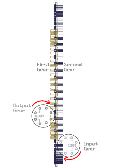
Gearbox example #2: The Input and Output gears rotation needs to be interchange from the Gearbox example #1, thus still using the Input gear as the point where the force is applied into the system as seen in the drawing bellow. However now a downward pushing force is exerted on the First gear tooth. Note that the red arrow on the Output gear doesn't actually represent the direction that the gear rotates, rather it depicts the direction of the counteracting force created by a Load/restriction. When using such an arrangement, an efficiency of 94% is achieved since the Input gear's pushing force is now performed in a downwards manner which is exactly how the lever & weight embodiment #2 operates thus using the same formula.
GEARBOX EXAMPLE #2
There are two other functions that the lever & weight system can provide, as explained in Chapter #1C - EX E and EX F, the third class lever can only serve two functions as depicted above, thus the two other function are when a second class lever system is used, such as in EX G and EX H (Chapter #1C) where the Effort point is now further away from the fulcrum than the Load point, as can be seen on the next two examples bellow..
Lever & weight embodiment #3- Another function that the system can serve is when interchanging the point where the force is applied into the system and interchanging the direction of the forces from embodiment #1. Therefore, now the Input side is exerting a downward pushing force on the lever and the Output side an upward pushing force. It is obvious that the system will be 94% efficient since it is the same physical unit as embodiment #1 but used backwards, thus the opposite result must occur. The same formula as #1 embodiment needs to be used since the weights are in balance when at the upper stroke. Experiments conducted on this lever arrangement demonstrates that when the weight attached to the rope end (now the Output) is positioned at its upper position it will move downward until the lever reaches the upper position (where the balance occurs) thus lifting the weight on the longer lever (now the Input) meaning that the Input side is now weaker than the Output side thus the system efficiency must be proportionally the opposite result of embodiment #1 resulting in a 94% efficiency.
Lever & weights embodiment #3
And finally, Lever Embodiment #4- The last function that the mechanism can provide is achieved by only interchanging the point where the force is applied into the system from embodiment #1 as in the drawing bellow. This is performed by attaching the rope to the longer lever instead of the shorter lever and using it as the point where the force is applied into the system. Therefore, the Input is still performing an upward pushing force and the Output still performing downward force but the Input side is now located on the longest lever. The real-life experiment conducted on this lever arrangement confirms that the Input is stronger than the Output and that the balanced point now occurs at the lower stroke and is the reason why it needs to be configured using the same formula as in embodiment #2, although now the system has an efficiency of 107% since the Input pushing force is performed in an upward manner. We did not prevail a formula for this embodiment since it uses the same exact function and formula as used for the embodiment in Chapter #4 - the Custom hydraulic lever embodiment #3 reversed.
Lever & weights embodiment #4
The gearbox can also provide two more functions:
Gearbox example #3: Another function the gearbox can serve is by Interchanging the point where the force is applied into the system and also changing the Input and Output gear rotation from the gearbox example #1, thus now the Input gear is exerting a downward pushing force on the Second gear's tooth which is the reason why the system is 94% efficient. Note that the red arrow on the Output gear represents the counteracting force of the Load and not its actual rotation. The formula used is the same as in embodiment #1 since the weakest point of the system is when used at upper operating angle.
GEARBOX EXAMPLE # 3
Gearbox example #4: Finally, the last function that the gearbox can serve is achieved by interchanging the point where the force is applied into the system from the gearbox embodiment #1, thus using the Input gear (on the right) as the point where the force is applied into the system and use a C.W rotation now providing an upward pushing force on the Second gear's tooth. It can be noted that the red arrow for the Output gear doesn't show the actual direction of the gear but rather demonstrates the counteracting pushing force direction caused by a Load. It is obvious that the efficiency is 107% since the Input gear pushing force is still performed in an upward manner. The same formula as in embodiment #2 is used since the weakest point of the system still occurs at the start of the stroke.
GEARBOX EXAMPLE #4
To resume, the lever & weight and the gearbox embodiments #1 and #2 are considered as third class lever systems serving the first two different functions and must be combined to provide an overall system efficiency of 100%. Although they are configured using slightly different formulas.
The lever & weight and the gearbox embodiment # 3 and #4 are both considered as second class lever systems serving the two other function that the system can provide and also result in an overall system efficiency of 100%. However, the same physical embodiment is used for all four functions that it can provide where the over all system efficiency is equal to 100%.
The embodiment # 2 example is also used to demonstrate that the system MA is affected when only interchanging the pushing force direction which confirms that more force is provided when the pushing force is performed upwardly (as per embodiment #1) than when performed in a downward manner as per embodiment #2.
The Custom mechanisms provide an unbalanced distribution of power between the functions it can serve while the conventional mechanisms provide a balanced distribution of power in every function it can serve.
The same rules apply to every other Custom mechanism such as in the Custom Spur type gearbox (see "Gearbox" page) and the Custom Cage type gearbox which are designed to operate using the same principle.
In order to provide concrete proof that the Custom mechanisms can achieve over unity, another embodiment type was fabricated and experimented on and is presented in the next Chapter. The experiment consists of using a hydraulic cylinder connected to a lever as the Input side of the system and the Output side is used to lift a weight attached to the other end of the lever. They provide unarguable facts that the phenomenon discussed above actually occurs. We can perform a live presentation on every embodiments presented on this website so you can see for yourself that the Custom mechanisms designed by Motion X are performing exactly as explained herein.
CHAPTER #4 - The Hydraulic lever Systems
To help demonstrate the differences and advantages between the common and the Custom mechanisms and to continue explaining the reasons why the Custom mechanisms are configured using a different formula than the common mechanisms, we fabricated and performed experiment on the next embodiments presented.
The experiment consists of measuring how much pressure (PSI) is required for the cylinder to lift (or to be in balance with) a specific amount of weight. The cylinder PSI value provides an accurate way of comparing both systems. First a demonstration on the conventional mechanism having a 1:1 ratio and a system MA of 1 is presented where the resulting PSI value is used as a reference point indicating the where the forces are in a balance.
The first part of the video bellow video depicts an experiment conducted on the conventional hydraulic lever system and the second part is the same experiment conducted on the Custom hydraulic lever system:
The drawing bellow depicts the conventional system used in the first part of the video.
EX 1- The common Hydraulic lever system:
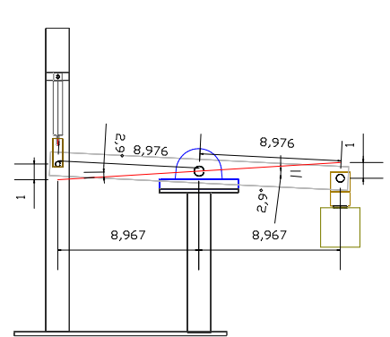
Two pillow block bearings (in blue) are installed at the centre of the lever and are fixed to a post (in black). A shaft is inserted into the bearings and used as the fulcrum point for the lever (in light grey). On the left extremity of the lever is attached a rod end yoke (in brown) of a cylinder (in grey) where the cap end is fixed to a supporting frame (in black). On the right extremity of the lever is attached a weight (in brown). The lever system has a 1:1 ratio since the Input and Output have the same distance from the fulcrum (8.976"), thus providing a system MA of 1. If the cylinder rod end moves 1" downwards the weight moves 1" upwards measured vertically (V.D). The lever orientation at the end of the 1" stroke is depicted by the red line. It can be noted that the lever operates evenly above and bellow the horizontal axis resulting in an average pushing force performed perpendicularly to the horizontal axis which is classified as a conventional mechanism.
The tests simply consist of measuring how much pressure is needed at the cylinder to hold the load at various positions within the 1" stroke. The same cylinder and weight are used on the Custom mechanisms presented bellow therefore, the cylinder PSI value is used to provide a fair comparison and an accurate means of configuring the Custom system MA.
To calculate the average system MA of the common hydraulic embodiment, the "conventional lever law" formula (as in chapter 1 explanation 3) is used. However, if the MA at the start or at the end of the stroke is to be calculated separately then the top right picture in the drawing below must be used. The vertically oriented red arrow (on the top right picture) represents the pushing force angle and its direction, it can be interpreted as either the cylinder downward pushing force or either as the load attached to the lever pulling down on the lever.
 .
.
To calculate the system MA of the common hydraulic lever EX #1 when at the lowest operating angle (start of the 1" stroke). Note that to make it easier to calculate we will pretend that the cylinder provides 100 lbs of force.
1- Torque present at fulcrum:
= 100 lbs (force applied into the system) / 8.967" ("H.D" between the cylinder rod end to fulcrum)
= 896.7 In/lbs of torque is present at the lever fulcrum.
2- Force at the lever end: (using the formula in reverse)
= 896.7 in/lbs / 8.967" H.D
= 100 lbs of force at lever end.
Therefore, with the cylinder providing 100 lbs of force to the left side of the lever can lift a 100 lbs weight (really is in balance with the 100 lbs Output weight). It can be concluded that the system has an MA of 1 since 100 lbs (force put in) divided by 100 lbs (force coming out) = 1 MA, and because the Effort and Load points have the same H.D from the fulcrum when at the upper or at lower operating angles.
To calculate the efficiency, the Vertical Distance (working distance) travelled by the cylinder and the weight are used. The cylinder moves down 1" (measured vertically) while the weight moves up 1" (measured vertically), therefore:
3-Efficiency = (1" Input V.D / 1" Output V.D) X [(1 MA @ start + 1 MA @ end) / 2] X 100 (to convert into a percentage)
= 100%.
The result might seem to be obvious to a mechanically inclined person, but it is necessary to explain this aspect in order to be able to compare and understand how the Custom mechanisms are configured.
The first part of the video demonstrates that 160 PSI is needed at the cylinder in order to hold/lift the Load at any point within the 1" stroke. This value is used as the reference point to identify at which operating angle the Custom system has an MA of 1, thus providing an accurate way to compare both mechanisms.
The Custom Hydraulic Lever system as seen on the second part of the video above has the same Input and Output working distances travelled (1.015" V.D), thus providing a fair comparison between the conventional and the Custom mechanisms.
Ex 2-The Custom Lever System embodiment #2
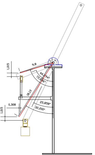
The drawing depicts the same specifications as the unit seen in the video.
The drawing above depicts the Custom hydraulic lever system where two pillow block bearings (in blue) are supported by posts (in black). A shaft is inserted into the bearings and creates the fulcrum point of both levers (in light grey). The two levers (short and long) are bolted together at the fulcrum (they are considered as one lever). At the end of the shorter lever is attached the rod end (in brown) of a cylinder (in grey) and the cap end is secured to a mounting bracket and supported by the horizontal frame (in dark grey). At the end of the longer lever is attached a weight (in light brown). The reason why the lever extends upward is to obtain a balance when the lever is empty, this is achieved by adding the proper size weight depicted by the black circle located at the end of the lever uppermost extremity. This is done in order fairly compare this embodiment with the common lever system which is also in equilibrium when the lever is empty since the fulcrum point is at the centre.
Let's first use the "wrench formula" to demonstrate that it cannot be used to calculate the Custom mechanism:
@ Lower operating angle:
1- Torque present @ fulcrum:
= 100 lbs (force applied to the system) X 8.973" H.D [Sin 66.294 degrees X 9.8" = the Horizontal Distance (H.D) between the Effort point and the fulcrum] = 897.3 In/lbs of torque present @ fulcrum
2- Force at lever end (longer lever):
= 897.3 In/lbs divided by 7.91" H.D Load point to fulcrum (Sin 25.858 X 18.13")
= 113.44 lbs present at the longer lever end.
3- MA = 113.44 / 100 = 1.1344 MA
Since we know the in Common system 160 PSI is required at the cylinder in order to balance with the weight and resulting in a system MA of 1, we can now calculate the required cylinder PSI needed in order to lift the weight according to the conventional formula:
4- PSI = 160 PSI / 1.1344 MA
= 141 PSI needed at the cylinder to hold the weight when at start of the stroke.
Although the video demonstrates that 134 PSI is needed at the cylinder to hold the weight when at the start of the stroke and not 141 PSI, thus the result provided here is not accurate.
Let's try it @ upper operating angle Still Using The "Wrench Formula":
1- Torque Present At Fulcrum:
= 100 Lbs X 9.3534" H.D (Sin 72.636 degrees X 9.8" - Horizontal Distance From Effort To Fulcrum At End Of Stroke)
= 935.34 In/Lbs Of Torque At Fulcrum
2- Force at lever end:
= 935.34 in/lbs / 9.661 H.D Load point (Sin 32.2 X 18.13")
= 96.84 lbs at lever end.
3- MA = 96.84 / 100 = 0.9684
4- PSI = 160 PSI / 0.9684 MA
= 165.2 PSI. Although as the video demonstrates, only 158 PSI is needed when the lever is operating at the upper stroke therefore the formula is wrong again. It can also be seen in the video that the PSI gauge is very sensible, if the Load is lightly moved by hand the PSI gauge quickly reacts, thus only a few PSI means a great deal.
If calculating the efficiency using the wrench formula results values:
5- Overall Efficiency = [(1.015" / 1.015" Input V.D and Output V.D) X (1.1344 MA lower X 0.9684 MA upper) X 100 (to convert into percentage)
= 1 X 1.098 X 100
= 109.86% Efficient.
The wrench formula is not accurate when using such an arrangement, it even contradict its own rules since when configuring the efficiency, it should always be 100% where as above = 109.86%. The formula doesn't work because the Input pushing force directions is performed upward in addition to the strategic combination of lever angles and lengths used. It can also be noted that the stroke doesn't occur evenly above and bellow the lever's horizontal axis which is the reason why it is considered to be a Custom lever system.
To proper way to configure the system is shown in Chapter #3, using the same formula as the Custom Lever & Weights embodiment #1 since the upper stroke is the point were the two forces are the closest to have an MA of 1, and also since it represent the same function as used in #1; the Input pushing force is performed in an upward manner while the Output pushing force is performed in a downward manner and that the power applied into the system is performed on the shorter lever. It can be seen in the video it takes more PSI at the cylinder to lift/balance with the weight when at the end of the stroke than when at the start.:
@ upper stroke:
Step #1- Input = Sin 72.636 X 9.8" = 9.3534" H.D
Step #2- Output = Sin 32.2 X 18.13" = 9.661" H.D
Step #3- 1.0144 (9.8" / 9.661") X 0.5159 (9.3534" / 18.13")= 0.5233
Step #4- 0.96816 (9.3534" / 9.661") X 0.54 (9.8" / 18.13")= 0.5233
Step #5- MA @ upper stroke: 0.5233 (Step #4) / 0.5233 (Step #3) + 0.008 (Cylinder 9 degrees of vertical = 1 - Sin 90 - 9 degrees = 0.008)
= 1.008 MA.
Note that in the Step #5 we also need to add the cylinder angle (which is not included in the drawing due to the limited space available) since the formula consider that the push is performed in a vertical manner while here the cylinder push is not performed exactly equal to the vertical axis which also affects the system MA.
- PSI = 160 PSI / 1.008 (as per Step#5) = 158.6 PSI. As it can be seen on video, 158 PSI is needed at the cylinder to balance with the load when at the end of the stroke thus confirming that the formula is accurate at least for the end of the stroke.
@ start of stroke:
Step #6- Input = Sin 66.294 X 9.8" = 8.973" H.D
Step #7- Output = Sin 25.858 X 18.13" = 7.9073"
Step #8- = 9.661" (Step #2) - 9.3534" (Step #1) = 0.308" + 8.973"(Step #6)= 9.281" (See chapter #5 Example #1 which confirms that this Step needs to be calculated this way).
Step #9- MA = 9.303" (Step #8) / 7.9073" (Step #7) = 1.17 MA + 0.01 cylinder 8 degrees of vertical (1 - Sin of 90 - 8)
- PSI = 160 / 1.18 = 135.5 PSI, which is pretty close to what can be seen on the video where it takes 134 PSI at the cylinder before the weight starts to creep down when at the start of the stroke. This confirms that the formula used to calculate the system MA @ the start stroke is also accurate.
Step #10- Overall system MA = [1.008 from Step #5 + 1.17 from Step #9] / 2 = 1.091 MA
Step #11- Efficiency= [1.015" (Output V.D)/ 1.015" (Input V.D)] X 1.091 from Step #10 X 100 (to turn into a percentage)
= 1 X 1.091 X 100
= 109.1 %
To provide even more proof and confirm that the Custom system can provide efficiencies over 100% we fabricated another embodiment (#3 presented next). Its system MA is also configured using the same formula as the Custom & Lever embodiment #1 (in Chapter #3) since the weakest point in the system also occurs at the upper stroke.
THE CUSTOM HYDRAULIC LEVER SYSTEM embodiment #3
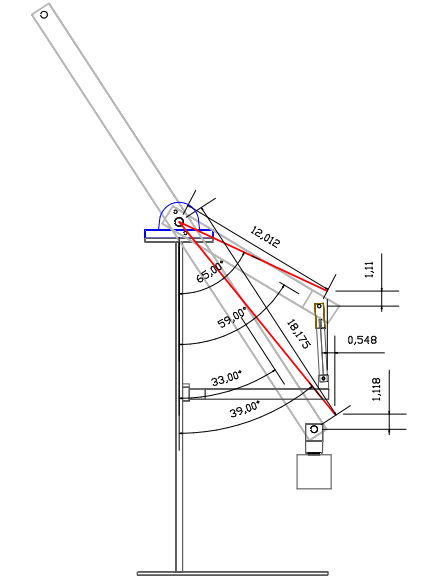
The next video depicts the embodiment #3 as per drawing above.
It is demonstrated in the drawing above that this embodiment utilises different lever angles and lengths than in the embodiment #2, which help to confirm that the formula presented is accurate.
As can be seen in the video when operating at upper stroke it is the point where the two forces are the closest to have an MA of 1, thus we use the same formula as in Lever & weights embodiment #1 and #3 we need to start with:
To calculate @ end of stroke:
Step #1- Input = Sin 65 X 12.012" = 10.8866" H.D
Step #2- Output = Sin 39 X 18.17" = 11.434" H.D
Step #3- 1.0506 (12.012" / 11.434") X 0.599 (10.8866" / 18.17")= 0.6295
Step #4- 0.952 (10.8866" / 11.434") X 0.661 (12.012" / 18.17")= 0.629
Step #5- MA @ Upper Stroke: Cylinder Angle = 90 - 10 Degrees = 80 Sin = 0.998, 1 - 0.98 = 0.02 + 0.629 (Step #4) = 0.65 / 0.629 (Step #3) =1.0334 MA
- PSI = 160 / 1.0334 = 154.8 PSI, As It Can Be Seen In Video It Takes 154 PSI At The Cylinder In Order To Balance With The Load When At Upper Operating Angle.
At Lower Operating Angle (Start Of The Stroke):
Step #6- Input = Sin 59 X 12.012" = 10.296" H.D
Step #7- Output = Sin 37 X 18.17" = 9.896" H.D
Step #8- MA @ Lower Stroke: 11.434" (From Step #2) - 10.8866" (From Step #1) = 0.548" + 10.296" (Step #6) = 10.844" (See Chapter #5 EX#1 it shows this step is necessary)
Step #9- MA @ Start Of Stroke= 10.844" (Step #8) / 9.896" (Step #7) = 1.10 + (Cylinder Angle = 90 - 22 Degrees = Sin 68 = 0.926, 1 - 0.926 =) 0.074 + 1.10 = 1.174 MA
- PSI = 160 / 1.174 = 136 PSI Where It Is Be Seen On Video Where It Takes 134 PSI To Balance With The Load When At Start Of The Stroke.
Step #10- Overall MA = 1.0334 MA (Step #5) + 1.174 MA (Step #9) / 2 = 1.1 Step #11- Efficiency = ) [1.118" Output V.D / 1.11 (Input V.D)] X 1.1 (Step #10) X 100 = 1.00107 X 1.1 = 110.7%
To Demonstrate What Would Occur If We Were To Use The "Wrench Formula".
MA At Upper Stroke: = 10.8866" (H.D Between The Effort Point And Fulcrum @ End Of Stroke) Divided By 9.896" (H.D Between The Restriction Point And The Fulcrum @ End Of Stroke) = 1.1 MA
Therefore = 160 PSI / 1.1 MA = 145.45 PSI but as can be seen in the second video, the cylinder needs 154 PSI and not 145.45 PSI which is A huge difference. This demonstrates one more time that the "Wrench Formula" cannot be used to calculate the MA of the Custom mechanisms.
The last Custom hydraulic lever embodiment to discuss is used to demonstrate what occurs in the system when interchanging the point where the force is applied into the system from the example above resulting in a Second-class lever system an operates exactly like in the Lever & weight embodiment #4 in Chapter #3. Therefore, using the same formula as in the Lever & Weights embodiment #2 since now when operating at the lower operating angle it is the point where the two forces are the closest to an MA of 1.
THE CUSTOM HYDRAULIC LEVER - EMBODIMENT #3 REVERSED
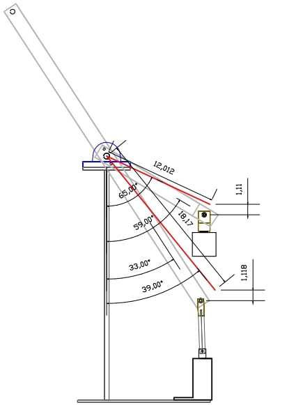
As can be seen on the drawing above, the lever angles and the distances from the Effort-Load points to the fulcrum are exactly the same as in the hydraulic lever embodiment #3 above in fact the same unit is used but the cylinder is now connected to the longest lever and the weight now attached to the shorter lever and consequently changes the cylinder pushing angle to be performed at slightly different angle than in embodiment #3 above. It can be seen in the next video; the weakest point now occurs at the start of the stroke.
To calculate @ lower operating angle (start of the stroke) since it is the closest point where the two forces are the closest to have an MA of 1 :
Step #1- Input = Sin 33 X 18.17" = 9.896" H.D
Step #2- Output = Sin 59 X 12.012" = 10.296" H.D Step #3- 1.2138 (12.012" Output actual lever length /9.896" Step #1)) X 0.5667 (10.296" Step #2 / 18.17" Input actual lever length)= 0.687 Step #4- 1.04105 (10.296" Step #2 / 9.896" Step #1) X 0.661 (12.012" Output actual lever length/ 18.17" Input lever length) = 0.68814
It can be noted that step #3 and #4 are slightly different from previous systems, and the explanation for this change in the formula is explained in Chapter #3 example #2.
Step #5- MA @ lower stroke: 0.68814 (Step #4) /0.687 (Step #3)= 1.002 But also need to add for the cylinder angle = 1 - (Sin 90 - 21)= 0.018 +1.002 (Step #5) = 1.02 MA
-PSI = 160 psi / 1.02 MA = 156 PSI. It can be seen in the video that it takes 154 PSI at the cylinder in order to hold/balance with the weight which is quite accurate.
At Upper operating angle (end of stroke):
Step #6- Input = Sin 39 X 18.17" = 11.435" H.D
Step #7- Output = Sin 65 X 12.012" = 10.886" H.D
Step #8- 10.296" (Step #2) - 9.896" (Step #1) = 0.4" + 11.435" (Step #6) = 11.835" Note; always use the bigger value between Step #1 and Step #2 as the first value to be entered in the formula since we need to reset the MA of 1 (point of equilibrium) reference point since the Input and Output H.D do not have the same lengths.
Step #9- 11.835" (Step #8) / 10.886" (Step #7) =1.09 MA + cylinder angle 90 -16 degrees = Sin 74 = 0.96, 1 - 0.96 = 0.04 + 1.09 =1.13 MA (See Chapter #5 Example #1 to understand that this step is necessary)
-PSI = 160 / 1.13 = 141 PSI which is the same as seen on the video when the system is operating at the upper stroke.
As it can be seen in the video, the system is now weaker at the start of the stroke compared to hydraulic lever embodiment # 3 where the system is stronger at the start of the stroke. The Lever & weight embodiment #2 and #4 (Chapter #3) also have the weakest point occurring when operating at the start of the stroke which is the reason why we didn't provide a video for these embodiments since it can be figured out that those 3 mechanisms share the same characteristics.
When using this formula, the cylinder pressures are matching what occurs in real life confirming that it is definitely accurate, and it also confirms that strongest point in the system always occurs on the side where the pushing force is performed upward.
Step #10- system MA = 1.05 MA (Step #5) + 1.13 (Step #9)] / 2 = 1.075 MA
Step #11- System Efficiency = 1.118" (Output V.D) / 1.11" (Input V.D) = 0.993 X 1.075 MA (Step #10) X 100
= 106.75 % efficient but only If we use the cylinder pushing in an upward manner on the lever.
Note that the efficiency isn't exactly as the embodiment #3 above due that the cylinder angles are not exactly the same, but it can be concluded that the system efficiency would be exactly the same if both embodiments had the a vertically pushing force, although have opposite weakest points when at the start and when at the end of the stroke. In embodiment #3 it takes 154 PSI at the end of the stroke to balance with the weight while it takes 154 PSI at the start of the stroke in embodiment #3 reversed.
It is also obvious that the system efficiency would be 93.25% if we were to fabricate an embodiment #4 where only the pushing forces directions would be interchanged from the example above. Therefore, the cylinder pushing force would be exerted in a downward manner and still connected to the longest lever, and where a spring (Output) used as an upward pushing force and attached to the shorter lever. Thus it is just a matter of using the cylinder (Input) in embodiment #4 to replace the weight (Output) in the embodiment #3 and since the weight was weaker in embodiment #3, it then means that the cylinder would be proportionally weaker than in embodiment #3, thus resulting in a 93.25% efficiency (106.75 + 93.25) / 2 = 100% overall system efficiency. Note that the embodiment #4 also represented the same function as used in the Example #3 in Chapter #3.
It can be noted that the Custom lever & weight and the gearbox embodiment #1 and #3, and the Hydraulic lever #2 and #3 are all configured using the same formula. While the Custom hydraulic #3 reverse, the Custom lever & weight and the gearboxes #2 and #4 use a slightly different formula. Every mechanism utilises the same values to be entered into the formula, they are just moved around in order to suite for the different functions the system can serve.
The Custom gearboxes can be used in many various applications while there are not really any applications that the lever system can be used for, they were used to explain how the Custom gearboxes were conceived and operate, and also to confirm that the only the formula presented herein can be used to configure the Custom mechanisms.
CHAPTER #5
Embodiment fabricated that help concocted the formula discussed above
This chapter is used to demonstrate how the formula presented herein was created based on the result of experiments conducted on many different mechanisms. We started by trying different formulas using the trial-and-error method until finding a formula that coincides with every single experiment conducted on the Custom mechanisms. It took us many years of failure to find the proper formula. This chapter also offers useful details not mentioned anywhere else on this website.
Example #1
.
This first example is used to confirm that formula - STEP#8 need to be used like demonstrated above.
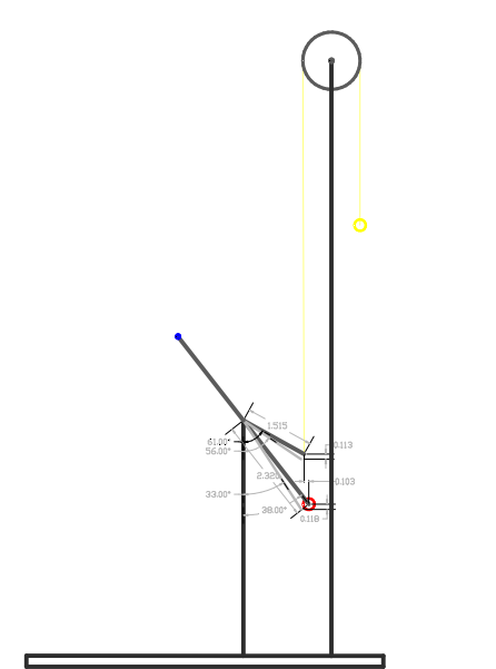
The drawing above depicts a lever system which has similar specifications than the wrench formula example used in chapter #2. A 1.5" lever (in black) is used as the Input side of the system. The red sphere depicts the Output weight, the yellow sphere represents the Input weight and illustrates the end of the stroke where both weights are in balance, while the rope is represented by a yellow line and the pulley is the dark grey circle on top. The levers drawn in light grey depicts the orientation of the lever when at the lower stroke.
The same size weights are used, thus at the end of the stroke the system MA is 1 where the Output point is located 0.103" H.D further than the from the fulcrum than the Input point which again contradicts the wrench formula. It can also be seen that the Output weight has a working distance of 0.118" (V.D) while the Input weight has a working distance of (0.113" V.D). Therefore, it can be concluded that the efficiency is over 100% since the start of the stroke has a system MA greater than 1.
The same formula as in the lever & weight embodiment #1 and #3 (in Chapter #3) is used since the balanced point in occurs at the upper stroke.
To configure the system we need to start by configuring the upper stroke since is the point of equilibrium:
Step #1- Input = Sin 61 X 1.515" = 1.325" H.D
Step #2- Output = Sin 38 X 2.32" = 1.428" H.D
Step #3- 1.061 (1.515" /1.428) X 0.572 (1.325" / 2.32") = 0.6059
Step #4- 0.92787 ( 1.325" / 1.428") X 0.653 (1.515" / 2.32") = 0.6059
Step #5- MA @ end stroke: MA = 1 since 0.6059 VS 0.6059 means equilibrium or a balanced state.
@ Start of stroke:
Step #6- Input = Sin 56 X 1.515" = 1.256" H.D
Step #7- Output = Sin 33 X 2.32" = 1.263" H.D
Step #8- 1.428" (from step 2) - 1.325" (from step 1) = 0.103" + 1.256" (Step #6) = 1.36" Step #9- MA @ upper stroke = 1.36" (Step #8)/ 1.263" (Step #7) = 1.08 MA
This example confirms that Step #8 needs to be used as shown where we subtract Step #2 from Step #1 and add the difference is added to Step #6. This is done in order to reset the equilibrium point and in order to reset the MA of 1 reference point. If we would simply use 1.256" (step #7) / 1.263" (Step #6) H.D at start of stroke, the MA would equal 0.99 MA which is inaccurate, it doesn't make sense since it states that the Input is weaker than the Output while in real life the Input is at its strongest point. In fact, when at the start of the stroke a 7 grams weight can be added on top of the Output weight in order to be in balance with the Input weight.
We can do a live presentation of any embodiments on this website free of charge if you don't believe this phenomenon is really happening in real life experiments.
Step #10- Overall MA = (1 MA Step #5 + 1.08 MA Step#9) / 2 = 1.04 MA or
Step #11- = [(0.118"-Output V.D / 0.113" Input V.D) + 1.04 Step #10] / 2 X 100 = 1.044 X 1.04 X 100
= 108 % (efficient theoretically).
If using the "wrench formula" when @ upper stroke = 1.325" (Input H.D) / 1.428" (Output H.D) = 0.93 MA. Therefore, according to the wrench formula, the lever would not be in a balanced state when oriented at the upper operating angle but in reality they are in balance.
The next embodiments are used to explain how the formula was developed. Experiments were conducted on these systems and the results were used to find the proper formula.
EX A-
When the system is in balance the Input and Output Horizontal Distances (H.D) from the fulcrum are not the same length:
The next embodiments are slightly different from the lever systems used above, they only depict the lever when oriented at a particular angle and don't show the lower and upper stroke point. Therefore, only the first part of the formula is needed in order to know if the weights are in balance or not. Every example uses different lever angles consequently changing the H.D values, which helped to find the proper formula since various conditions are prevail.
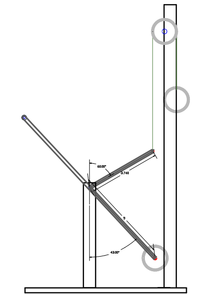
The system was first fabricated with one lever having 3.74" in length and the other lever having a 5" length, and then the levers were orientated at different angles until the equilibrium point was found (as depicted above). To calculate the system:
Step #1- Sin of 60 X 3.74" = 3.24" H.D (Input)
Step #2- Sin of 43 X 5" = 3.41" H.D (Output)
Step #3- 1.097 (3.74" / 3.41") X 0.648 (3.24" / 5") = 0.711
Step #4- 0.95 (3.24" / 3.41") X 0.748 (3.74" / 5") = 0.711
The results of step #3 and step #4 are the same which means that the system is in a balanced state (or has an MA of 1) and is also what occurs in real life.
The same formula than in lever & weight embodiment #1 and #3 (in Chapter #3) is used but because the system is only used at one particular angle and not used with a lower and upper operating angles, we then have to determine in which class the system is classified, in this case a third class lever system is used since the Input point is located closer to the fulcrum than the Output point.
The Output point is (3.41" H.D - 3.24") = 0.17" further away from the fulcrum than the Input point and the weights are in balance, therefore contradicting the lever law and the wrench formula where the MA = 3.24" / 3.41" = 0.95 MA which is quite far from being at the equilibrium point. Note that the step #3 and #4 values are NOT used to configure the system MA, they are used to precisely determining where the equilibrium point occurs as will be demonstrated in the next examples.
Ex B-
Using the same lever lengths but oriented at different angle and both weights are still in balance
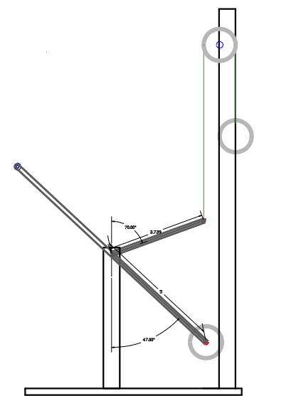
Step #1- Sin 70 X 3.74" = 3.514" H.D
Step #2- Sin of 47 X 5" = 3.656" H.D
Step #3- 1.023 (3.74" / 3.656") X 0.703 (3.514" / 5") = 0.719
Step #4- 0.96 (3.514" / 3.656") X 0.748 (3.74" / 5") = 0.719
Again Step #3 and #4 have the exact same values which means the system is in a balanced state and is what also occurs in real life. The same formula as in the lever & weight embodiment #1 and #3 is used since a third-class lever system is used.
If using the wrench formula: 3.514" / 3.656" = 0.96 MA which is wrong since the Input and Output are in balance at this precise lever orientation as in what occurs in real life experiments conducted on this system.
EX C-
Same thing for the next system, the balance occurs when both levers' H.D have different distances:
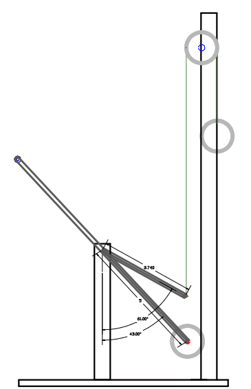
Step #1- Sin 61 X 3.74" = 3.27" H.D
Step #2- Sin 43 X 5" = 3.41" H.D
Step #3- 1.097 (3.74" / 3.41") X 0.654 (3.27" / 5") = 0.717
Step#4- 0.959 (3.27" / 3.41") X 0.748 (3.74" / 5") = 0.717
Same results again meaning the two weights are in balance at this lever orientation.
If using the wrench formula: 3.27" / 3.41" = 0.96 MA which is again wrong, the Input is not weaker than the Output weight, they are in balance.
Ex D-
Another balanced system fabricated where the result occurring in real life are the same as the formula results:
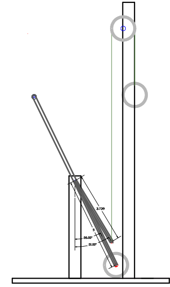
Step# 1- Sin 31 X 3.739" = 1.926" H.D
Step# 2- Sin 26 X 5" = 2.192" H.D
Step# 3- 1.7058 (3.739" / 2.192") X 0.385 (1.926" / 5") = 0.6571
Step #4- 0.8787 (1.926" / 2.192") X 0.748 (3.739" / 5") = 0.6571
The Step #3 and #4 still have the same exact result which means that both weights are in balance when the lever is used at this operating angle which is also what occurs in real life.
There are plenty more third class lever embodiments that were experimented on where they have different lever lengths and angles combinations.
Next let's examine some systems that we know are not in balance, and as stated earlier step 3 and #4 should not have the same values:
EX E-
Unbalanced system
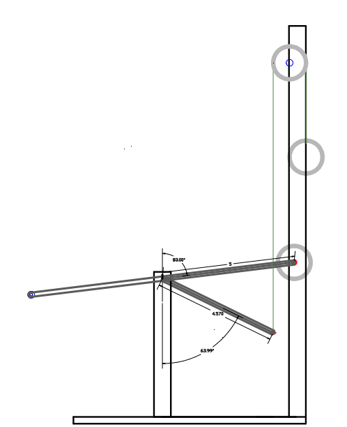
This lever system is not in a balanced state, it was fabricated, and the experiments results show that when the lever is oriented at this angle shown, the weight on the right (Input) is stronger than the other causing the lever to settle at another operating angle.
Step #1- Sin 83 X 5" = 4.963" H.D (Input)
Step #2- Sin 64 X 4.57" = 4.1075" H.D (Output)
Step #3- 0.92 (4.57" / 4.963") X 0.822 (4.1075" / 5") = 0.755
Step #4- 0.83 (4.1075" / 4.963") X 0.914 (4.57" / 5") = 0.759
It can be seen that the formula has been changed and using the same one as in the Lever & Weights embodiment #2 since the system is classified as a second-class lever system.
As you can see step #3 and #4 have different resulting values (0.759 - 0.755 = 0.004 difference), meaning that the weights are not in balance with each other. Although the system MA cannot be configured using those two values since it would equal 1.005 MA (0.759 / 0.755) which is not accurate since there the Input is located 0.8555" (4.963" - 4.1075) where it is obvious that the weights cannot be in balance with such a difference in H.D.
The difference between the two numbers precisely determines how far from the equilibrium point the system is operating.
Let's examine another example where there is more difference between the step #3 and #4 results.
Ex F-
Greater difference of unbalanced between both weights
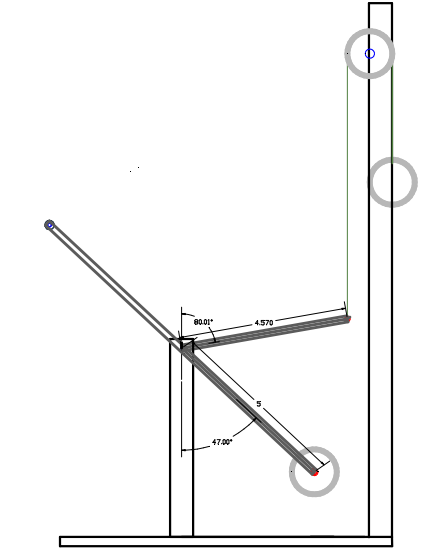
Step #1- Sin 80 X 4.57" = 4.5" H.D (Input)
Step #2- Sin 47 X 5" = 3.656" H.D (Output)
Step #3- 1.1 (5" /4.5") X 0.8 (3.656" / 4.57") = 0.88 Step #4- 0.8124 (3.656"/4.5) X 1.094 (5" / 4.57") = 0.8888
The greater the difference between step #3 and #4 (0.89 - 0.8888) = 0.009 difference means that the lever is further away from the equilibrium point than in EX-E above where it has 0.004 difference.
The same formula as in lever & weight embodiment #2 & #4 (in Chapter #3) is also used.
Now let's examine what happens if we use our formula in a conventional system where the balance point occurs when the Input and Output H.D have the same distances (as per wrench formula = MA of 1 or weights are in equilibrium).
EX G- The common system (equal H.D on Input and Output)
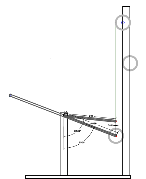
Step #1- Sin 84 X 4.57" = 4.545" H.D
Step #2- Sin 69 X 4.868" = 4.545" H.D
Step #3- 1.005503 (4.57" / 4.545") X 0.93364 (4.545" / 4.868") = 0.9388
Step #4- 1 (4.545" / 4.545") X 0.9388 (4.57 / 4.868) = 0.9388
This example confirms that if the same result are obtained for step #3 and Step #4 means that the system is in a balanced state. Although the system above cannot be used to design a Custom mechanism since the Input and Output have the same H.D which means the system is 100% efficient and is considered as a conventional lever system. It can be concluded that either the wrench formula or the formula we developed can be used to configure the common mechanisms. However, the conventional lever formulas cannot be used to configure the Custom mechanism, only the one we developed can be used.
The formula corresponds with every fabricated mechanism as demonstrated on this page. It is important to note that in every single embodiment used above, when the levers are oriented in such a way that the Input and Output H.D both have the same distances from the fulcrum, the weights will be in balance although are not classified as a Custom mechanism. As confirmed by many experiments when the right combination is used, there is also another point where the weights will be in balance and where the Input H.D and Output H.D have different distances, those system are classified as Custom mechanisms.
Motion X gearboxes are designed according to these principles and for that reason it provides an over unity system when using the function it was designed for.
If you have any questions or want us to perform a presentation free of charge, please contact us!
For any inquires please email us at: mechalldon@gmail.com