Please only watch the videos when directed, otherwise they will seem to be meaningless unless you are an expert in the field.
On this page the conventional and the custom gear-trains are compared by conducting different experiments on fabricated embodiments and measuring the power put into and coming out of mechanisms. After reading this document you will understand how to reduce fuel consumption in either automobiles, heavy equipment or small engines, increase electricity production in power plants or reduce energy consumption in industrial facilities by simply integrating the custom gear-trains in the system.
Note that the "Operation Basics" page should be read and understood before proceeding, unless you are a person skilled in the art.
The Custom gearboxes presented herein are Patented in the U.S.A and Canada. We currently only have prototypes fabricated and are seeking for investors to provide funding and have units professionally built to be installed in power plants in order to provide a power generating capacity increase up to 12% by simply integrating the gearbox into their system. This website discloses every aspects concerning the operation of the Custom mechanism in detail.
The Motion X Gearbox comprises a unique gear-set especially designed to achieve a superior efficiency over the conventional gear trains. Since it can achieve over unity, it can even be used to create a self-sustainable generator. Be part of the climate change solution, the energy crisis solution and help reducing pollution, contact us today! This is a great opportunity for investors in the energy sector!
We are willing to perform a presentation on every embodiments discussed on this website so you can see for yourself that over unity has been achieved and has also been harnessed.
The formulated combination of the pushing forces direction, the gears' operating angles and their radius provides a better performance than any conventional mechanisms when used the proper way. The Custom gear-sets are conceived to operate using different Circular Pitch (C.P) and tooth shapes on each gear, in terms providing an unbalanced power distribution transfer from the Input side to the Output side of the system.
When applying a force at the Drive side of the gearbox, the special combination amplifies the exerted power by 12%. However, when reversing the gearbox rotation it results in the reverse effect, a 12% power loss occurs, thus providing an unbalanced power distribution from the Input to the Output of the system. When both functions are combined it results in an overall system efficiency of 100% and confirms that the law of conservation of energy is still respected.
The conventional gear-set requires the same Circular Pitch (C.P) on each gear and also they need to have the same tooth shape in order to have fluent contact between the gears' meshing tooth. Therefore, resulting in a balanced power distribution transferred to the Output regardless of the function used, thus resulting in 100% efficiency in every different function the gearbox can provide. Visit "Operation basics" page Chapter 1A for a detailed explanation on this subject.
To explain the operation and advantages of using this new type of mechanism, experiments conducted on both the Conventional and on the Custom mechanisms are demonstrated bellow and provides a mean of comparison between the two systems. Many different embodiments are presented on this website where different experiments are conducted to provides concrete evidence that the Custom mechanisms can achieve over unity (also been approved by engineers, contact us to view the certificates).
PEOPLE SKILLED IN THE ART CAN SKIP TO CHAPTER #3.
CHAPTER #1 - TERMINOLOGY USED FOR GEAR-TRAINS
1- TO CALCULATE EFFICIENCY;
The theoretic efficiency of any power transmitting systems such as a lever system, a tackle and block, a hydraulic jack or a gear-train must equal 100% (without including any friction generated within the unit). Watts or Horse Power (HP) or torque can also be used instead of Joules.
2-TO CALCULATE HORSE POWER;

The formula states that Power equals Torque multiplied by RPM divided by 5252.
3-TO CALCULATE WATTS;
Watts = Volts x Amps.
4- SPEED RATIO;
The speed ratio is used to configure the system's Mechanical Advantage (MA) on the conventional gear-set (the number of the Drive shaft revolution VS the number of the Driven shaft revolution).
- If the ratio is 1: 1, Ma = 1
- If the ratio is 2: 1; MA = 2
- If the ratio is 1: 2 (the Drive shaft = 1 turns and the Driven shaft = 2 turns); MA = 0.5
The speed ratio of a gearbox also represents the Drive/Driven shaft RPM or speed. For example, a gear set having a 1:1 speed ratio means that both the Drive and the Driven shafts are rotating at the same speed.
The gearboxes used in the next examples are all using a 1:1 speed ratio since it eases the understanding of the operation principle of and also provides a fair comparison of both types of mechanisms (conventional and custom).
Note that in this document we refer to;
- C.P as the Circular pitch
- H.D as the Horizontal Distance measured between two points
- V.D as the Vertical Distance measured between two points
- MA as the Mechanical Advantage
More terminologies are available on "Operation Basics" page Chapter 1A and should be understood before caring on.
CHAPTER #2 - THE COMMON GEAR-TRAIN
To fully understand how the Custom gearbox operates, the conventional mechanism operation has to be understood clearly.
It is well known that any conventional gear-set having a 1:1 speed ratio has an MA of 1 and a theoretic efficiency of 100% regardless of the function it serves. For example if we apply 100 Ft/lb on the Drive (Input) shaft of the conventional gear-set having a 1:1 ratio, a 100 Ft/lb will be transferred to the Driven (Output) shaft resulting in a 100% efficiency. If we were to reverse the rotation of Drive and the Driven end will result in the same outcome (100% efficiency). The Custom mechanism we developed works differently, one function provides a 113% efficiency while the other function has a 87% efficiency. Therefore, the overall system efficiency returns to 100% [(113% + 87%) / 2 = 100%]
As explained in the "Operation Basics" page in Chapter #1B and #1C, a gear-set can serve up to four different functions; two functions are obtained by interchanging the rotation of the Input and Output shafts. The other two functions are obtained by interchanging the point where the power is supplied to the gear-train between the Drive and the Driven side. When configuring the efficiency of the conventional mechanism, only one of these function needs to be considered since they all prevail at the same outcome, an efficiency of 100%. However, when configuring the Custom mechanism the efficiency of every functions need to be configured separately and then be combined to equal an overall system efficiency of 100%.
To demonstrate that the Custom gearbox has a better efficiency than the Common gearbox, tests are performed on both gearboxes and then the results are compared.
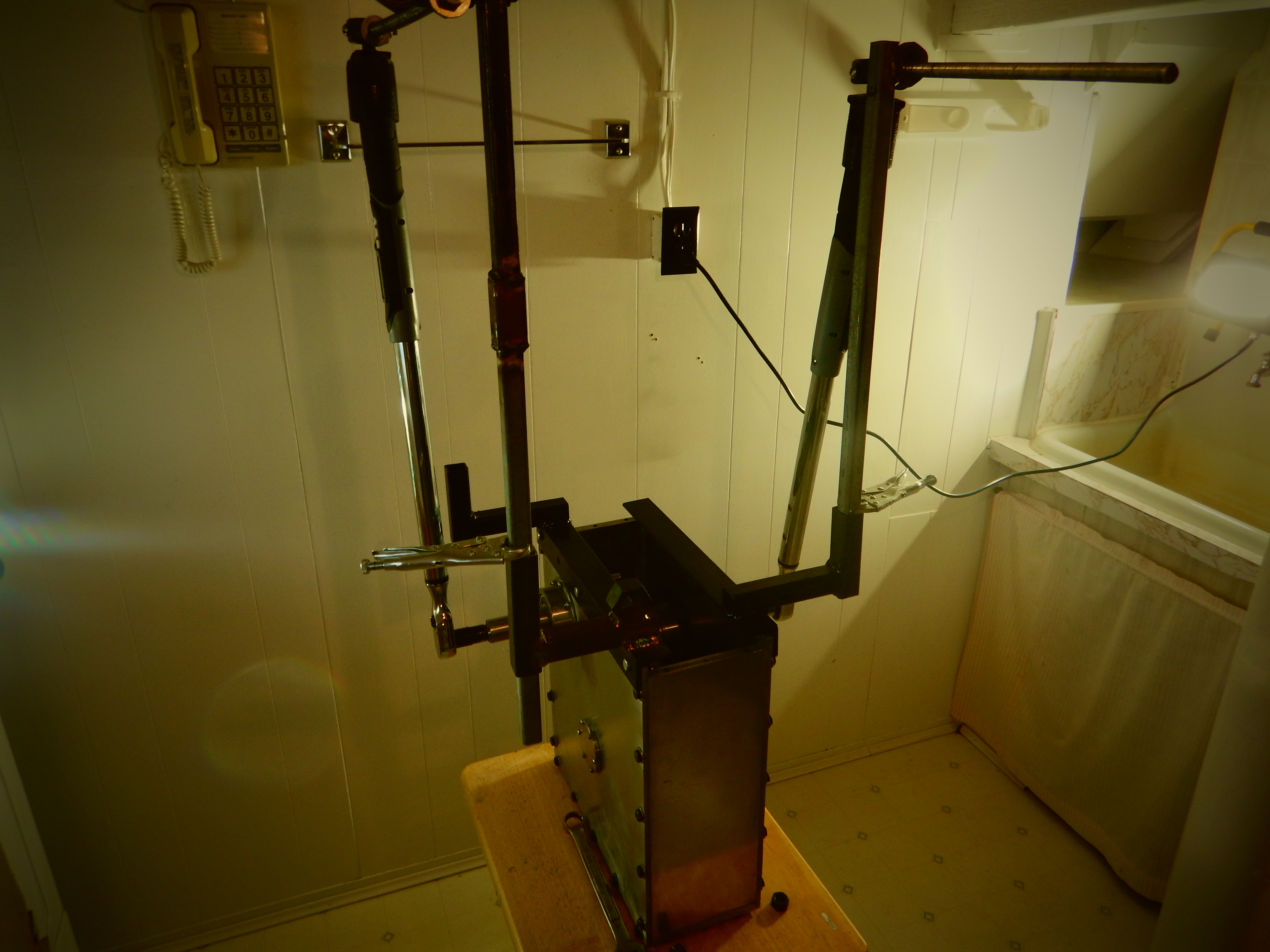
The first test consists of performing a torque test on the Common gearbox in order to provide theoretical efficiency. A torque wrench is installed at the Drive (Input) shaft and another torque wrench is installed at the Driven (Output) shaft. A force (in Ft/lb) is applied to the Drive gear by adjusting the tension on the torque wrench, the force is then transferred to the Driven gear where the other torque wrench is installed. In the next chapter the same test will be conducted on the Custom gearbox and then both results are compared.
The system efficiency can be configured by entering both torque wrenches reading values into the formula used bellow.
The next video depicts the torque wrench test performed on the Boston gearbox (a conventional 1:1 speed ratio gear-train).
The wrenches gauges readings in the video are;
-Torque wrench on the Drive shaft reads 10 Ft/lb.
-Torque wrench on the Driven shaft reads 10 Ft/lb.
We then enter these values in the next formula. Note that since a 1:1 speed ratio is used we enter a 1 as the RPM value:
To calculate the HP supplied to the Input; = 10 Ft/lb x 1 RPM / 5252 (as per formula in Chapter 1)
= 0.002 HP
To calculate the HP coming out of the Output; = 10 Ft/lb x 1 RPM / 5252
= 0.002 HP
To calculate efficiency; = Work Out / Work IN x 100 (as per formula in Chapter 1)
= 0.002 HP / 0.002 HP x 100
= 100%
If the operation of the Common gear-train is reversed by interchanging the point where the power is supplied from the Input (Drive) shaft to the Output (Driven) shaft. This fact is confirmed by the torque wrench test where it demonstrate that a balanced between the Input and Output forces occurs, thus the efficiency will remain the 100% regardless of rotation or where the point the power is supplied to the system. The results might seem obvious for a person skilled in the art since any conventional systems have an efficiency of 100% but is an important aspect to consider when configuring the Custom gear-trains as will be explained later.
It can be noted that when performing this test, the gears do not actually rotate thus no friction is generated resulting in the theoretical efficiency (ideal value). In order to configure the real efficiency a Dynamo-meter test needs to be performed.
The Common gearbox dynamo-meter test;
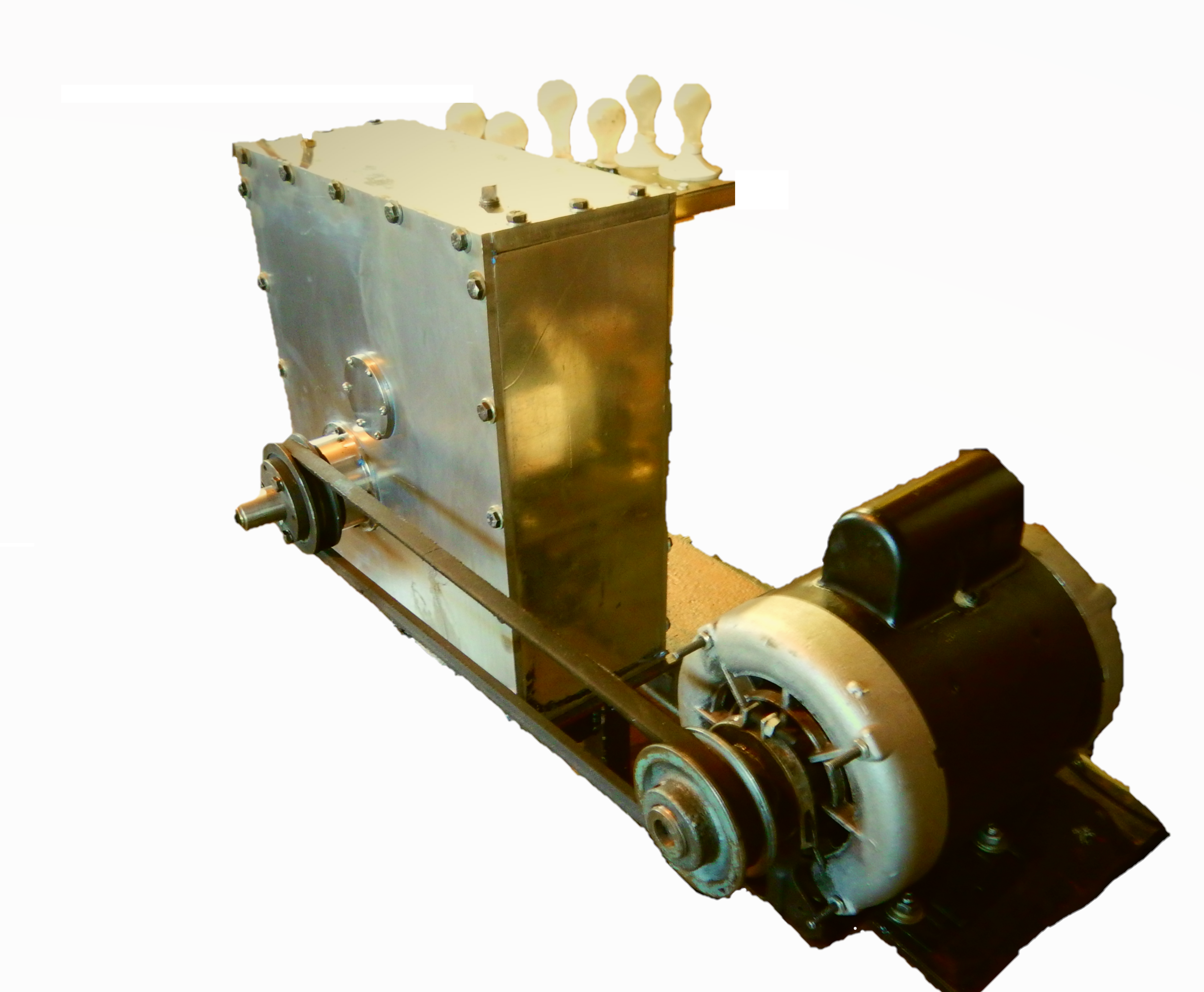
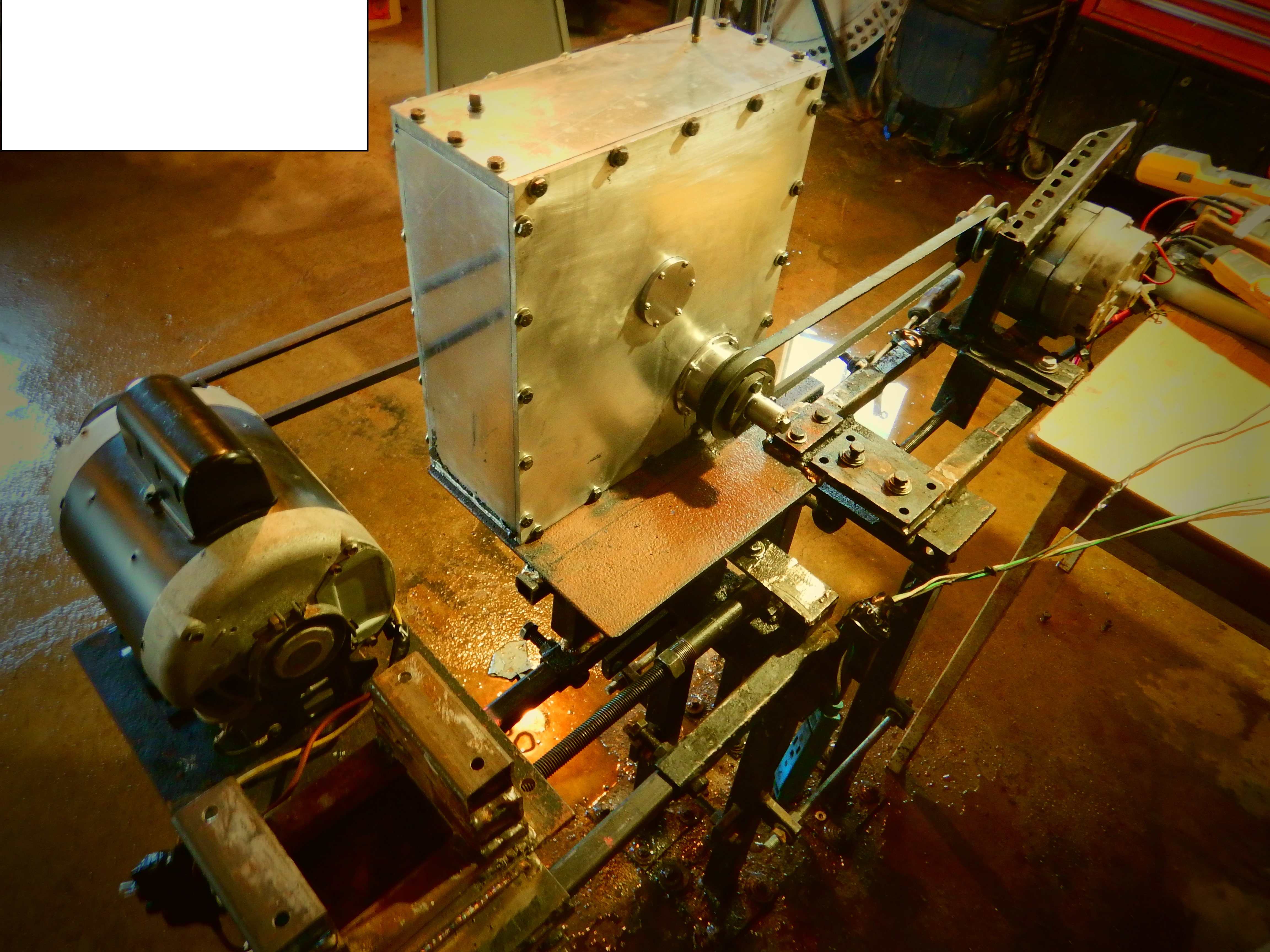
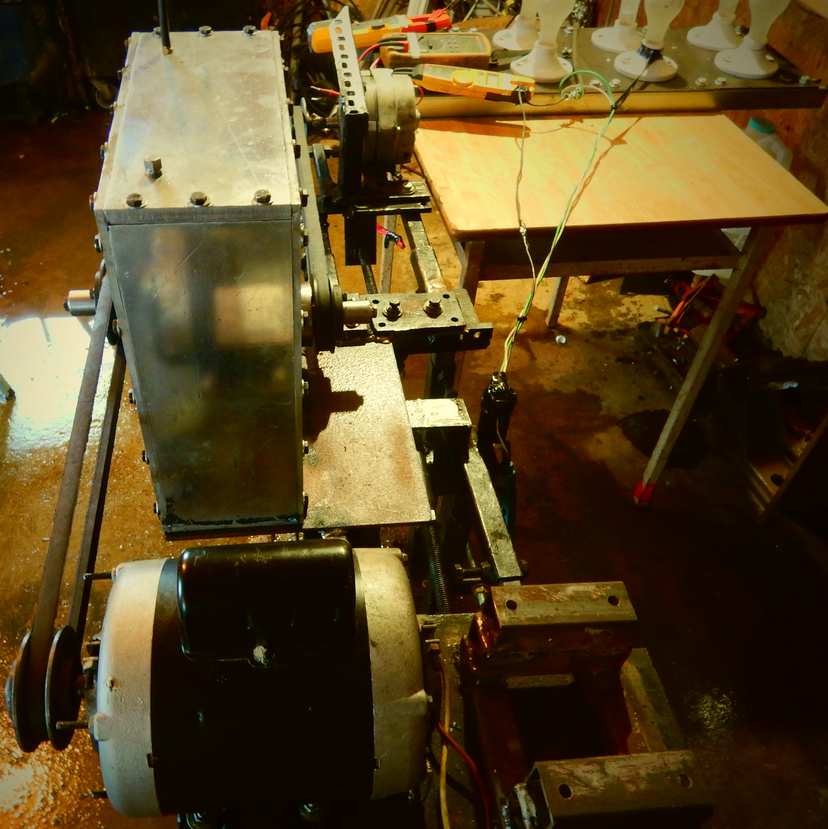
The Dynamo-meter test consists of measuring the power put into and coming out of a system at a given RPM. It comprises an electric motor coupled to the gearbox Input shaft and connecting a generator on the Output shaft. An amp meter and a voltmeter are connected to the Motor and provide a way of measuring how much power is supplied to the system. A separate meter set is connected to the generator to measure how much power is coming out. The meter values are used to configure how much power (Watts) the motor draws VS how much power the generator produces. Note that the generator speed is also monitored to ensure an accurate and fair comparison between both gearboxes.
The Boston gearbox consists of an Input gear (Drive), and an Output gear (Driven) as shown on the drawing below. To provide a fair comparison, two Boston gearboxes are connected when performing the test since the Custom gearbox consists of two gear sets.
The Common Gearbox internal drawing;
The power applied and coming out is measured in Watts using the Volt and the Amp meters.
The meters are individually tagged to show which value they are measuring. The RPM meter is held by
hand on the generator shaft. A 120 Volts ac / 10 Amps electric motor, and a 120 Volts ac / 30 Amps generator are used. It is not necessary to connect a voltmeter to the motor since it is connected to a household plug supplying a constant 120
Volts.
Please only watch the first part of the video where the dynamo test is performed on the Boston gearbox. In the next Chapter we will refer to the second part where the dynamo test is performed on the Custom Motion X spur type gearbox where both results will then be compared.
The table shows the values recorded in the first part of the video;
- "NO LOAD" = There is no load on the generator (the light bulbs are turned "OFF").
- “6 Bulbs" = There is a load on the generator, the light switch is turned "ON" and the six 100 Watts (ea) light bulbs are lit.
- "M" = Motor 2 HP @ 1750 RPM
- "G" = Generator 120 VAC\ 30 Amps
- "RPM" = Speed
- "Ratio" = The gearbox's speed ratio.
The Common gearbox parameters:
.jpg?timestamp=1642682589830)
The Efficiency is calculated when under a 6 light bulbs Load. The the generator RPM is also recorded and will be referred to when comparing the Custom gearbox results in the next Chapter.
- The Motor draws; 120 Vac x 16.5 Amps = 1980 Watts
- The generator produces; 58 VAC x 3.7 Amps = 214.6 Watts
- The System's Efficiency = Power Out \ Power In x 100
= 214.6 \ 1980 X 100 = 10.84 % is the efficiency of the motor, the gearbox and the generator.
CHAPTER #3
THE MODIFIED SPUR TYPE GEAR-TRAIN
The type of gear-set that we offer transfers the power supplied and coming out of the unit differently than in the common gear-sets. Instead of having the exerted force distributed evenly through the operable functions, the applied force is distributed in an unbalanced manner between two operable functions that the unit can serve as demonstrated bellow (visit "Operation basics" page for a detailed explanation).
The Custom gearbox also has a 1:1 speed ratio although when applying 100 Ft/lb of torque on the Drive (Input) shaft, it provides 113 Ft/lb at the Driven (Output) shaft. Therefore, when applying 100 Ft/lb to the Driven (Output) shaft (instead of the Drive shaft), it only provides 87 Ft/lb to the Drive (Input) shaft, thus when combining both ways it can be used the efficiency equals 100%.
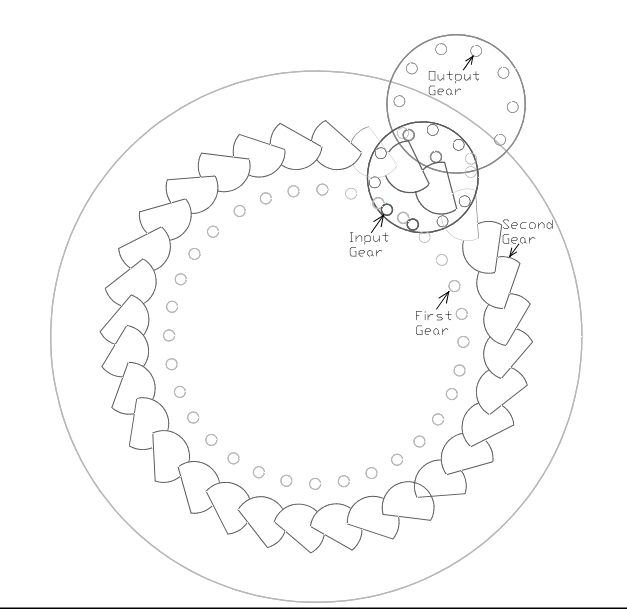
The Motion X gearbox presented herein comprises an Input gear engaging the First gear thus forming one gear-set. The First and the Second gears are fabricated as one unit (such as a conventional double-sided crown gear) and are used as an idler gear. The Second gear engages the Output gear thus forming another gear-set. Both the Input and Output gears have 10 teeth, the First and the Second gear have 32 teeth each. This combination provides a gear-train having a 1:1 speed ratio.
The next video depicts the torque wrench test performed on the Custom Spur Type Gearbox:
To calculate the system MA using the torque wrenches readings in the video;
- The gauge on torque wrench installed on the Input shaft reads = 11.5 FT/lbs
- The gauge on the torque wrench installed on the Output shaft reads = 13 Ft/lbs
- MA = 13 Ft/lbs / 11.5 Ft/lbs = 1.13
Therefore, when applying 100 Ft/lb at the Input shaft, 113 FT/lb is transferred to the Output shaft, and since the gearbox has a 1: 1 ratio (as shown in the video), the theoretical efficiency is 113% (not considering the friction). It can also be concluded that when 113 Ft/lbs of torque is applied to the Driven end only 87 Ft/lbs comes out at the Drive end. Therefore, when combining two (opposite) functions together results in 100% efficiency.
When Drive gear is used as the Input: = (100 / 13) X 11. 5 = 113 Ft/lbs
When the Driven gear is used as the Input: = (100 / 11.5) X 13 = 87 Ft/lbs
When compared to the Boston gearbox torque wrench test it can be seen that they both use the same speed ratio (1:1), However resulting in a different system MA which is not supposed to occur according to the lever law.
The next test consists of conducting the dynamo test on the Motion X gearbox where the results provide the real efficiency (including the system friction) .
The dynamo-meter test performed on the Custom Gearbox;
Please watch the second part of the video bellow.
The values recorded in the video are:
.jpg?timestamp=1642717792704)
To calculate the Efficiency when the system is under load (6 light bulbs):
It can be noted that when conducting this test, the generator has 1655 RPM (when under load), and when test was performed on the Boston gearbox the generator RPM was 1665 thus providing a fair comparison between both systems.
- The Motor draws; 120 Vac x 13.9 Amps = 1668 Watts
- The generator produces; 56.8 VAC x 3.6 Amps = 204.48 Watts
- The system's Efficiency = Power Out \ Power In x 100
= 204.48\ 1668 = 12.26 % is the motor, gearbox and generator efficiency, but since the same motor and generator is used on both experiments, we can use both gearboxes values and determine the gearboxes efficiencies.
The Boston gearbox system has a 10.84 % (as per chapter #2) while the Motion X gearbox system has 12.26% Efficiency. Therefore: =12.26% / 10.84% X 100 = 113.09% efficient, but we also need to consider that the "Boston" gearbox isn't 100% efficient as per picture bellow where the Boston gearbox specifications is: 3.675 Hp applied to the input, equals 125 in/lb. @ 1750 RPM.
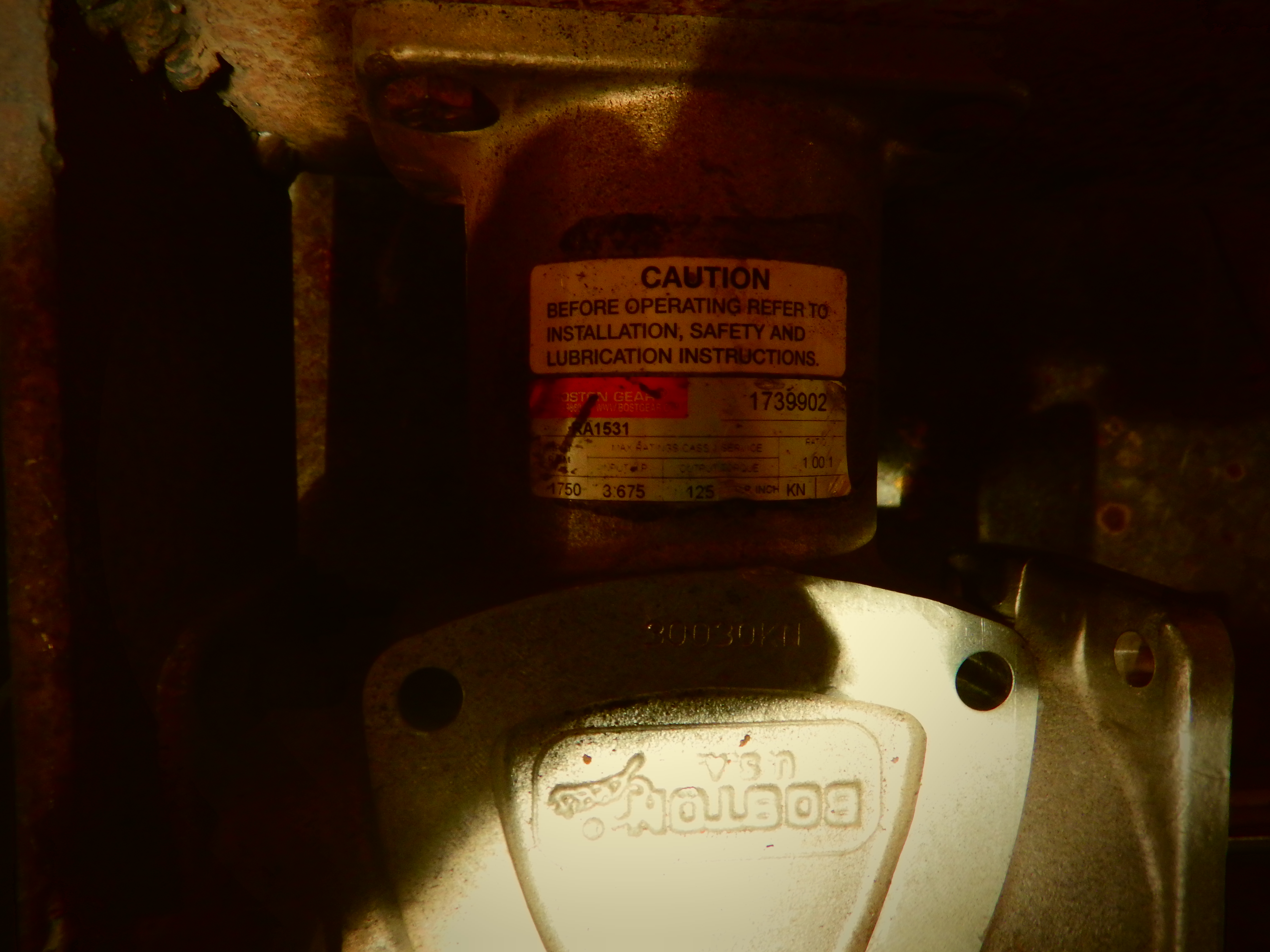
To configure the Boston Gearbox efficiency the torque formula is used but first we need to convert the applied HP value into in/lbs:
= 5252 x HP / RPM
= 5252 x 3.675 HP / 1750
= 11 Ft/lb. x 12 = 132 in/lb.
-Efficiency = Force out / Force in X 100
= 125 in/lbs / 132 in/lbs X 100
= 94.6 % efficient including friction.
-Therefore, to configure the real efficiency of the Motion X gearbox;
= 113.09% - 5.4% (100 - 94.6)
= 107.69 % efficient including friction
The next experiment (Direct version dynamo test) is use to confirms that the results above are in fact accurate, it consists of performing the dynamo test on the motor and generator only (excluding the gearbox from the system).
Please watch the next video "Direct Version Dynamo Meter test":
The values recorded in the video are:
.jpg?timestamp=1642718123757)
Note that the generator turns 90 RPM higher than it was on the gearbox tests since 1665 RPM was the best efficiency achievable when performing the test on the Boston gearbox due that it is harder for the motor to turn the Boston gearbox, thus slowing down the RPM. Then I had to make adjustments in order to have the Custom gearbox to turn the generator at approximately the same speed as the Boston gearbox in order to have a fair comparison. Also, this version's best efficiency achievable is at this speed.
- The Motor draws; 120 Vac x 11.8 Amps = 1416 Watts.
- The generator produces; 60 VAC x 2.7 Amps = 162 Watts.
- The Efficiency = Power Out \ Power In x 100 = 162 Watts \ 1416 Watts X 100
= 11.4 %
To compare with the Motion X gearbox;
= 12.26% (Custom gearbox dynamo test results) / 11.4% (from above) X 100 = 107.54% efficient. Comparing the Custom gearbox with either version (Boston gearbox or Direct) confirms that it has a 107.5% efficiency.
The efficiency of the Boston Gearbox can also be confirmed
= 10.84% / 11.4 % (direct version system efficiency) X 100 = 95.1 % Efficient just like stated on the manufacturer specifications.
See Chapter #5 for the method used to calculate the efficiency of the Motion X Custom gearbox and furthermore details on the subject.
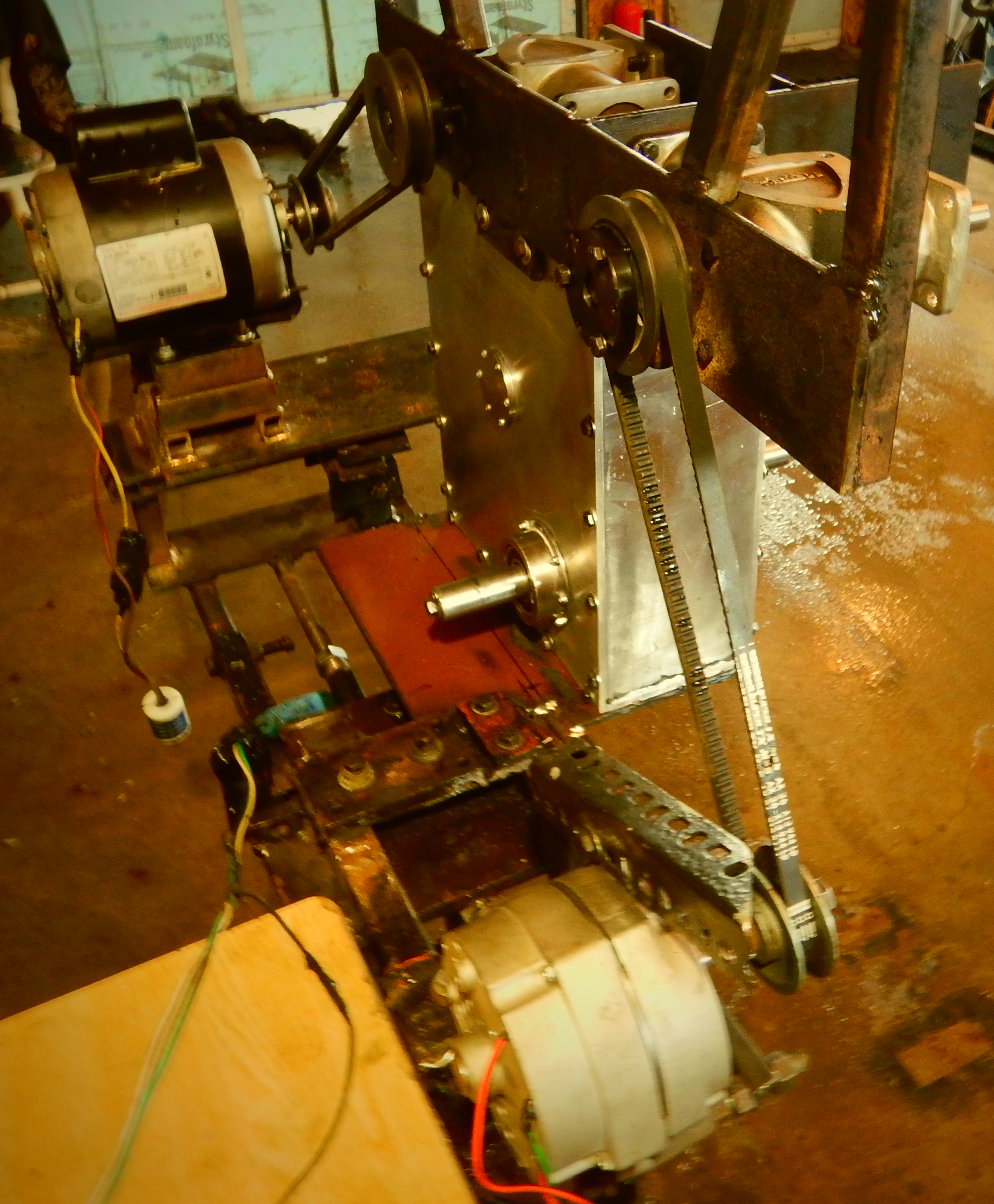
CHAPTER #4 - THE CAGE STYLE CUSTOM GEAR BOX
Bellow is the first Custom gearbox that was conceived where a 107% efficiency is also achieved including the system’s friction. It consists of the most primitive types of gears (Cage gears). Continued research and developments provided us with much more efficient models, one of them is used as an example bellow. We apologise for the poor model/video quality, but it still demonstrates the results obtained when using our gearbox.
Please watch the video bellow:
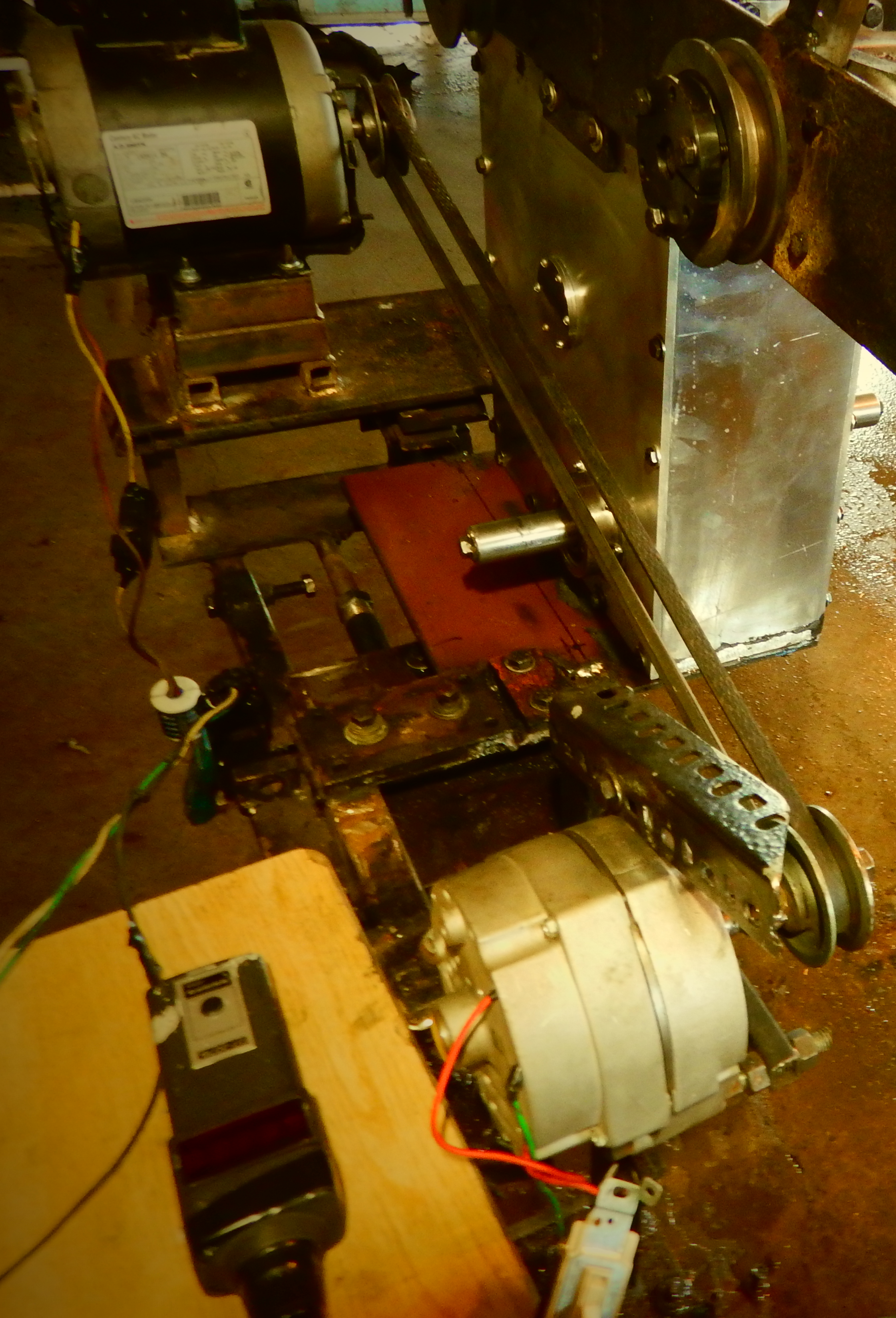
The first part of the video is the dynamo test conducted on the Direct version, while the second part of the video depicts the same test conducted on the Custom Cage type gearbox. The experiment procedure is the same as used on the system above.
The same motor, generator and the same length of belts are utilised on both experiments (note that another motor is used than when performing the dynamo test in Chapter #3).
The gearbox has a ratio of 1:1 which is used to fairly compare to the "Direct" version since the motor is directly connected to the generator where they both rotate at the same speed. The Custom gearbox is an open-type consisting of an Input gear (Drive gear), a First gear (idler gear #1), a Second gear (idler gear #2) and an Output gear (Driven gear), thus also consist of two gear-sets
- The yellow volt meter gauge is connected on the motor and measure amps.
- The green and yellow volt meter gauge is connected to the generator output to measure amps.
- The blue volt meter gauge is connected to the generator output and measures volts.
- The RPM meter is held by hand on the generator output shaft.
- A 120 Vac / 10 Amps electric motor, and a 120 Vac / 30 Amps generator are used.
- A voltmeter is not necessary for themotor since it is connected to a household outlet supplying a constant 120 Volts.
In the first part of the video "The direct version";
When the switch is turned "ON", the six 100 watts light bulbs are lit;
- the motor draws 8.6 amps;
- The generator turns at 1254 RPM and delivers 42 volts at 2.9 amps.
In the second part of the video "The Custom Cage gearbox version";
When the switch is turned "ON", the six 100 watts light bulbs are lit;
- The motor draws 8.3 amps.
- The generator produces 42 volts and 3.0 amps and turns at 1254 RPM.
The values are entered in the table bellow;
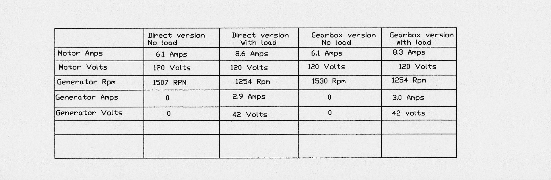
To calculate the systems' efficiency;
-Power IN "Direct" version where the motor draws 8.6 Amps x 120 Volts = 1032 Watts
-Power OUT "Direct" version where the generator produces 2.9 Amps X 42 Volts x 2.9 Amps = 121.8 Watts.
Compared with the Custom gearbox:
-Power IN: the motor draws = 8.3 Amps x 120 Volts = 996 Watts
-Power OUT: the generator draws 42 Volts x 3.0 Amps = 126 Watts.
Efficiency:
- Direct version system efficiency = 121.8 Watts / 1032 Watts X 100 = 11.8 %
- Custom Gearbox system efficiency = 126 Watts / 996 Watts X 100 = 12.65 %
- Therefore the Custom Gearbox efficiency = 12.65 / 11.8 X 100 = 107.2 %
By integrating the Custom gearbox between the turbine and the generator in any power plants by coupling increase the power generating capacity by 7%.
It can also be used to replace the common gearbox in any industrial application or to be added on the driveline of a vehicle to reduce fuel consumption.
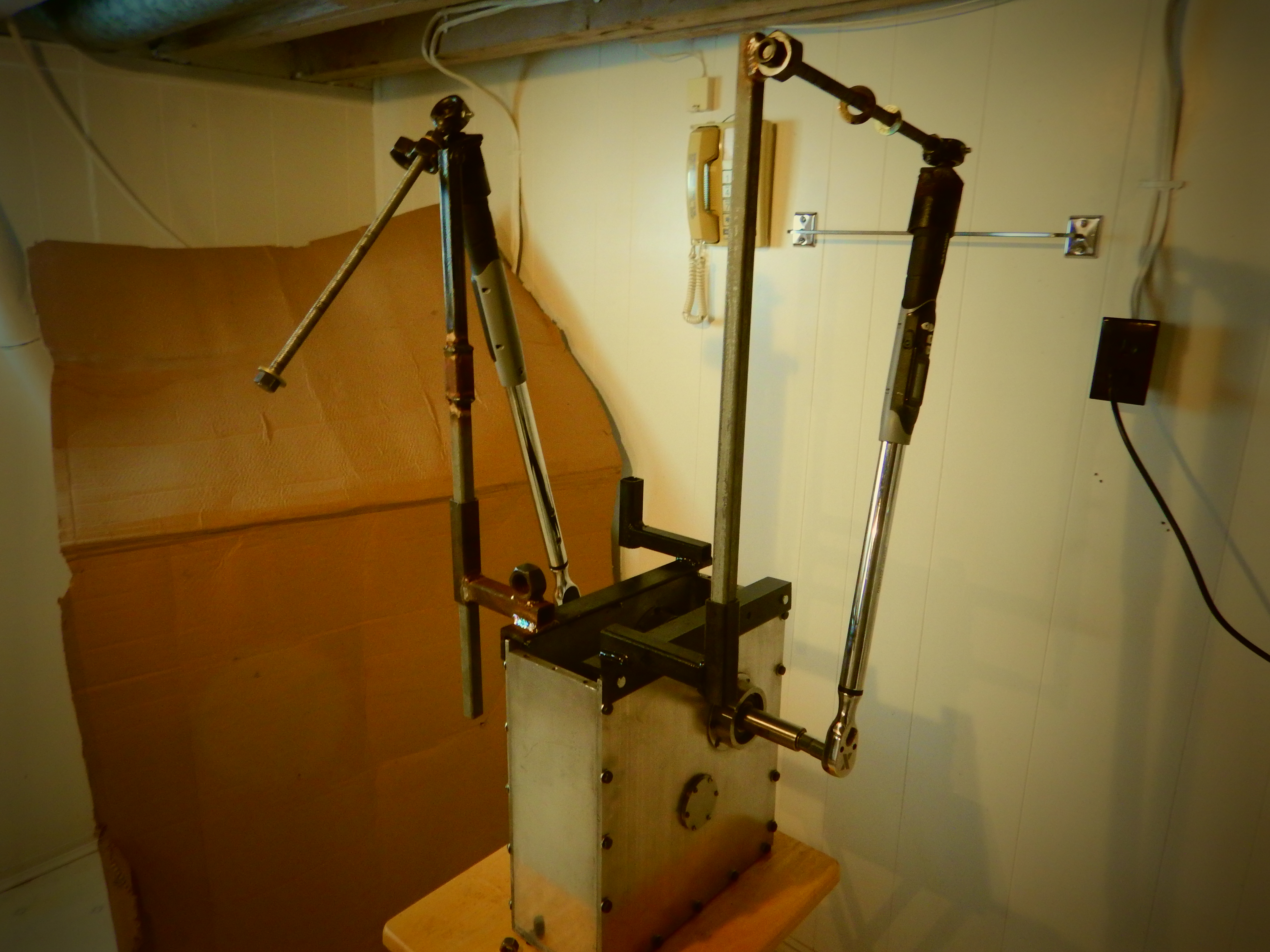
Torque wrench test on the Custom Cage type gearbox.
Note that the gearbox has been modified from the model discussed above due to the development and provides a better efficiency than the embodiment above.
Please watch the next video:
The method used is the same as the torque wrench tests performed on the gearboxes in Chapter #2 and Chapter #3.
The gearbox has a speed ratio of 1 to 1 as demonstrated in the video.
To calculate the performance using the torque wrenches reading values as per video:
= 38 FT/LB (Output reading) / 30 FT/LB (Input reading) X 100 (to convert into percentage)
= 1.26 x 100 = 126 % efficient.
If the power applied to the system is interchanged from the Drive shaft to the Driven shaft, the efficiency will only be 74% since if 38 Ft/lbs is applied to the Input only 30 Ft/lbs comes out at the Output. Therefore, combining the two functions the unit can serve result in a 100% overall system efficiency geometrically calculated (not including friction).
= [(126% + 74%) / 2] = 100
We can use the same coefficient of friction as on the Cage gearbox dynamo test above to configure the real efficiency (5.34% friction)
= 126.6 - 5.34 = 121.32% real efficiency since the same gearbox is used although Input Gear has been modified.
The efficiency table of various Common gear types;
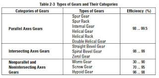
The table above is simply to demonstrate that gear-trains are very efficient, the worst type is the worm gear set. As you can see in the drawing bellow where the drive gear has the shape of a screw resulting in a lower efficiency due to that the power applied to drive gear is transmitted to the drive gear in a 100% sliding manner. The modified gear set gear-set has a sliding effect percentage proportional to the common spur gear set. Therefore, the loss due to friction is similar to a spur gear type.
CHAPTER #5 - METHOD USED TO CALCULATE THE CUSTOM GEARBOX EFFICIENCY
The method to calculate the efficiency of the Custom Spur gearbox presented in Chapter #3) is explained next but greater details are available on the "Operation Basics" page Chapter #3 - example Lever & Weight embodiment #4.
The gearbox mechanism bellow needs to be interpreted as a Second-class system since the Input side Horizontally measured Distance (H.D) from the fulcrum is greater than the Output side H.D.
The Custom Spur Type Gearbox (front view)
Note that only the gear-sets are shown.
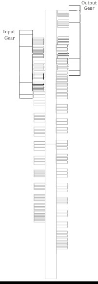
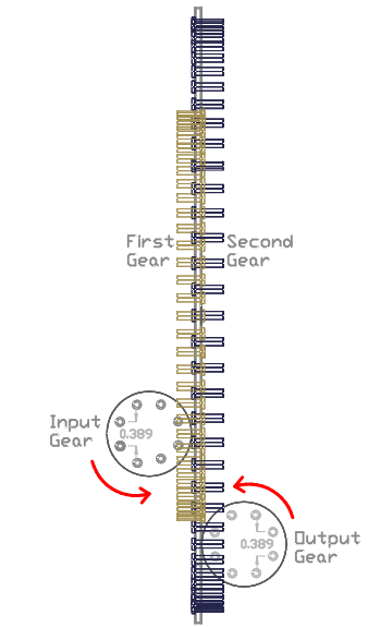
The Custom Spur Type Gearbox (side view)
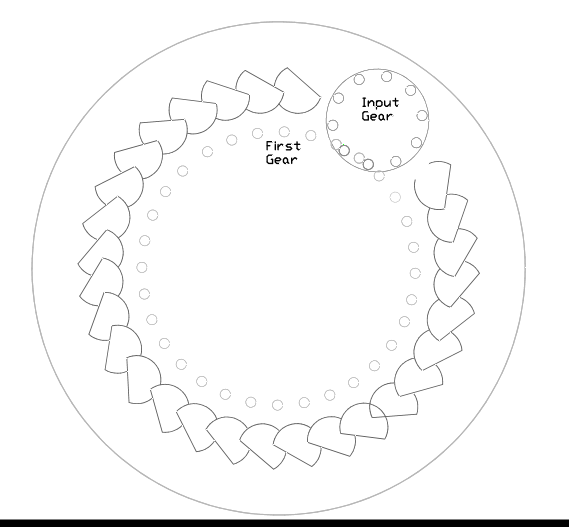
For ease of understanding, the gearbox has been separated into two sections: the Input/First gear-set and the Second/Output gear-set
Input/First gear set.
The Second/ Output gear-set:
The two drawings above depict the actual location and orientation of the gears within the gearbox, Although the method used to calculate the gear-sets MA requires that the pushing force needs to be performed in a vertical manner (explained on page "Operation Basics" Chapter #1A example #7). Therefore, the gear-sets need to be rotated until their pushing force angles (blue lines between the meshing gears on the drawing bellow) are averaging an orientation parallel to the vertical axis which provides the appropriate operating angle and the true working distance values to use in the formula.
The Input/First gear set rotated
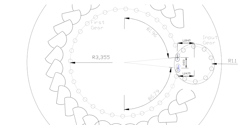
- Input gear radius = 1.1”
- Input gear average H.D = 1.041" [(1.0475" - 1.0345") / 2] + 1.0345"
- The Input gear working distance = 0.610" (V.D) - The Input gear is the Drive gear and rotates C.W
- First Gear radius = 3.355”
- The First gear operates from 86.79 degrees to 81.96 degrees measured from the vertical axis - The First gear is the Driven gear and rotates C.C.W.
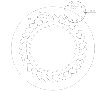
The next drawing depict the Second/Output gear-set when rotated so that the average pushing force (blue lines at the meshing lower and upper points) are equal to the gears' vertical axis.
The Second/Output gear-set rotated
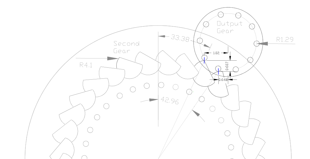
- Second gear radius = 4.1”
- The Second gear operates from 42.96 degrees to 33.38 degrees from the vertical axis. -The Second gear is the Drive gear and rotates C.C.W
- Output gear radius = 1.29"
- The Output working distance = 0.607" (V.D) -The Output gear average H.D = 0.85" [(1.02" - 0.648") / 2] + 0.648" -Output gear is the Driven gear and rotates C.W.
Note that the First and Second gears are mounted on the same shaft.
The power is supplied to the Input gear's shaft and is transferred to the First gear, after to the Second gear and finally the power comes out of the Output gear’s shaft.
The formula used to configure the gearbox is the same as on the page "Operation Basics" in Chapter #3 Lever & Weight embodiment #4. The First and Second gear need to be configured first since the gears depict the Second-class lever system and are the base (the heart) of the gearbox. We need to start calculating @ the Start of the stroke since it is the weakest point in the system:
The drawing bellow depicts the location and rotation of the Input and Output gears.
Step #1- Sin 86.79 degrees (lower operating angle) X 3.355" (First gear radius) = 3.349" H.D
Step #2- Sin 42.96 degrees X 4.1" (Sec rad) = 2.79" H.D
Step #3- (4.1" Sec rad / 3.349" Step #1) X (2.79" Step #2 / 3.355" First rad) = 1.018
Step #4- (2.79" Step #2 / 3.349" Step#1 X (4.1" Sec rad / 3.355" First rad) = 1.018
Step #5- MA @ Lower Stroke = 1.018 (Step #4) / 1.018 (Step #3) = 1 MA and means that both forces are balanced at this point.
@ Upper operating angle:
Step #6- Sin 81.96 degrees (upper operating angle) X 3.355" (First rad) = 3.22" H.D
Step #7- Sin 33.38 degrees X 4.1" = 2.2" H.D
Step #8- (3.349" Step #1 - 2.79" Step #2) + 3.22" (Step #6) = 3.8" (this step is explained in detail on page "Operation Basics" page Chapter #5 example #1)
Step # 9- MA @ upper stoke = 3.8" (Step #8) / 2.2" (Step #1) = 1.73 MA
Step #10- Overall system MA = (1 MA Step #5 + 1.73 MA) / 2 = 1.36 MA
Step #11- First/Second gear Efficiency = (0.610" V.D Input / 0.607" V.D Output) X 1.36 MA (Step #10) X 100 (to convert in a percentage) = 136.7 %
Since the Input and Output gears do not operate evenly above and bellow their horizontal axis, we also need to consider them since they do affect the system MA:
A- 100 In/lbs / 1.041" (Input gear average H.D) = 96.06 lbs
B- 96.0 lbs X 1.367 MA (overall First/Second gear MA- Step #11)) = 131.31 lbs
C- 131.31 lbs X 0.85" (Output gear average H.D) = 111.6 In/lbs
D- System Efficiency: since a 100 In/lbs applied to the system and that 111.6 is coming out we can conclude that the efficiency of 111.6%
As can be seen on the dynamo-meter test performed on the Spur type Custom gearbox, the real efficiency is equal to 107.54% efficient thus 111.6 - 107.54 = 4.1 % of friction occurring within the gearbox which is sometimes called the coefficient of friction.
To help confirm that the formula is accurate we will calculate the system where the reverse function is used. This is performed by reversing the rotation of the gears while still using the Input gear as the point where the force is applied into the system as shown in the drawing bellow.
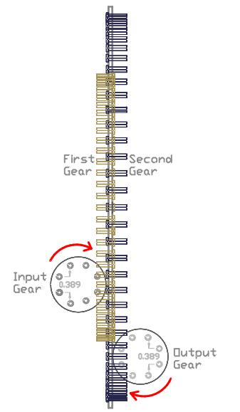
The next formula to use is explained in detail on "Operation Basics" page Chapter #3 - Lever & Weight embodiment #2 example which represents the opposite function as per drawing above:
As per experiments performed on this exact arrangement it is found that when the system is at its upper stroke it is now the weakest point in the system.
@ Upper stroke:
Step #1- Input= Sin 81.96 degrees X 3.355" = 3.22" H.D
Step #2- Output = Sin 33.38 degrees X 4.1" = 2.2" H.D
Step #3- 1.273 (4.1" Output rad / 3.22" from Step # 1) X 0.656 (2.2" from Step #2/ 3.355" Input rad)= 0.835
Step #4- 0.683 (2.2" from Step #2/ 3.22"from Step #1) X 1.22 (4.1" Output rad / 3.355" Input rad) = 0.835
Step #5- MA @ lower stroke = 0.835 (Step #4) / 0.835 (Step #3) = 1 MA (means the system is at a balanced state).
@ Lower Stroke:
Step #6- Sin 86.79 degrees X 3.355" = 3.349" H.D
Step #7- Sin 42.96 degrees X 4.1" = 2.81" H.D
Step #8- 2.2" (from Step #2) - 3.22" (from Step #1) + 3.349" (from Step #6) = 2.3" (see "Operation Basics" page Chapter #5 example #1 for more details)
Step #9- 2.3*(Step #8) / 2.81" (Step #7) = 0.78 MA @ upper stroke
Step #10- (1 MA (step #5) X 0.78 MA (Step #9) = 0.78 MA Overall system MA
Step #11- [(0.607 V.D Output / 0.610 V.D Input) X 0.78 MA = 0.777 MA
To account for the Output and Input gears:
A- 100 In/lbs / 0.85" (Average Output H.D) = 1.17 lbs
B- 1.17 X 0.777 MA (Step #11) = 0.89 lbs
C- 66.72 X 1.041" (Average Input gear H.D) = 90 In/lbs, therefore MA = 0.9 or 90% efficient
To calculate the overall system efficiency, we need to use the efficiency result of the example above (111.6%) and combine it with this example (90 %):
Overall system efficiency: 111.6 (%) X 90 (%) / 100 = 100 % efficient.
It can be concluded that when the system is used the way it was designed for (as discussed in the example above), it has 111.6% efficiency, although when the opposite function that the gearbox can serve is used, the system efficiency is 90%, thus when combined together result in a 100% efficient system.
The reason why the system is under 100% efficient is because the Input pushing force is now performed in a downward manner. .
As confirmed by many experiments conducted on many different fabricated mechanisms, it clearly demonstrates that the Custom mechanisms that we developed are over 100 % efficient if used the way it was design to operate but when using the opposite the function that the mechanism can serveresults in a system proportionally under 100 % efficient which then returns to overall system efficiency to 100% overall when combined.
CONCLUSION
Every embodiment in this web site are only prototypes but they are patented in the U.S.A and in Canada. We are looking for investors to bring the invention to the next level OR if you are interested into trying one out for your industry we can have one fabricated to fit your requirements. We can also license or sell the Motion X gearbox patents.
The Motion X Gearbox can be installed in any industrial complex to reduce energy consumption (between 7% and 12%, depending on which model is chosen). Our goal is to help out the best we can into ensuring a safe future for generations to come... A greener planet... help climate change and energy crisis issues...
If you have any questions or queries, we will be more than happy to reply with an answer. There is much more detailed information not included in this website, we believe we can answer any questions regarding these new mechanisms and their functions.
We are willing to do a live presentation of the tests performed herein free of charge so you can confirm for yourself these
gearboxes are really more efficient than any conventional gearbox.
For any inquiries please email us at: mechalldon@gmail.com
Donald Beaudet